CAD-CAM software provides significant advantages for automating the CNC machine programming and manufacturing process. One of the top advantages of using CAD-CAM software is the fact that it provides the necessary element of control to the process. Often times, machinists and programmers need a high level control to create efficient toolpath for 3 Axis parts. The solution is to use Surface Based Toolpaths.
CAD-CAM 3D Surface Based Machine Toolpaths Add Control
The BobCAD-CAM surface based machining module allows machine shops the benefit of using advanced strategies for 3 Axis programming. “Surface based toolpaths are extremely powerful providing 3 axis programmers the control and confidence to machine those difficult jobs that many shops turn away. At the same time gaining familiarity with these sophisticated strategies will shorten the learning curve when you make the transition into 4 & 5 Axis machining,” says Al DePoalo, voice of BobCAD AfterDark videos.
Subscribe to BobCAD-CAM's CNC Software Blog
Join your fellow manufacturers! Get BobCAD-CAM’s latest CAD-CAM articles straight to your inbox. Enter your email below:The Surface Based CAD-CAM Advantages Include:
1. High levels of control for CNC machining
2. Reduced cycle times on jobs that require surface machining
3. Surface-based machining is easy to use for mold & die machining
4. Superior machining operations with lots of options
5. Use t-cutters, dove, tapered & lollipop tools with surface based machining
Use T-Cutters, Dove, Tapered & Lollipop Tools with Surface Based Machining Operations
“Working with surface based paths offer additional tool types and compensation. This gives you the power to drive t-cutters, dove mills, tapered cutters and lollipop tooling to machine undercuts or back chamfers and radii,” adds DePoalo. Often times undercutting is a necessary part of 3D mold and die machining. The surface based machining operations are required for undercutting.
What Are The Surface Based Toolpaths?
If your CAM software can generate 3D toolpaths, does that mean it’s surfaced based? Not necessarily. What is likely happening is the surfaces or solids you’ve selected are being converted into 3D meshes which your CAM system uses to create toolpaths. This is where surface based toolpaths are different. Surface based toolpaths are generated using the surface data directly. Toolpath is created based on the selected drive surfaces. And so, what are drive surfaces? Drive surfaces are those surfaces you’ve selected that the toolpath will be driven along. How the toolpath is driven is based on which of the 7 surface based toolpath strategies you’ve selected and what options you chosen to work with. This is where you’ll find the user control and advantages of working with surfaces directly.
The surface based machining features found in the latest modules of BobCAD-CAM allow for a high level of user control. From providing the benefits of cut tolerance customizations to being able to determine the maximum distance between cut paths and surface handling parameters that allow for the merging of toolpath segments and how outside corners are handled, CAD-CAM should provide a significant amount of user control. For example, “toolpath linking” controls that are simply the method used to move the tool from one cut path to another efficiently. “The old saying use what you have holds true for so many things, but complex 3D machining isn’t one of them. Without surface based toolpaths there are many jobs that just aren’t profitable to run, if you can run them at all. This is one of the main reasons why so many shops are upgrading to these high end cutting strategies,” says DePoalo.
CAD-CAM surface based machine toolpath operations include:
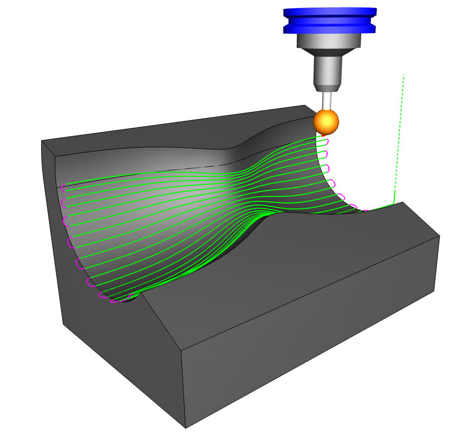
Flowline
Flowline, added in BobCAD-CAM Version 29, is one of the most popular surface based toolpaths because it’s so easy to set up. You simply select the surface that you want to machine and let the UV lines dictate the cutting direction of the path.
Similar to a morph toolpath, flowline provides a smooth flowing path that is driven based on the UV lines of the surfaces. Users can choose to cut along these UV lines or perpendicular to them.
“I find flowline to be simple to set up and use – unlike other toolpaths that require additional geometry, edge curves or drive surfaces to set up and program. With flowline, you just select the surface you want to work with and you’re right into the toolpath,” explains Al DePoalo.
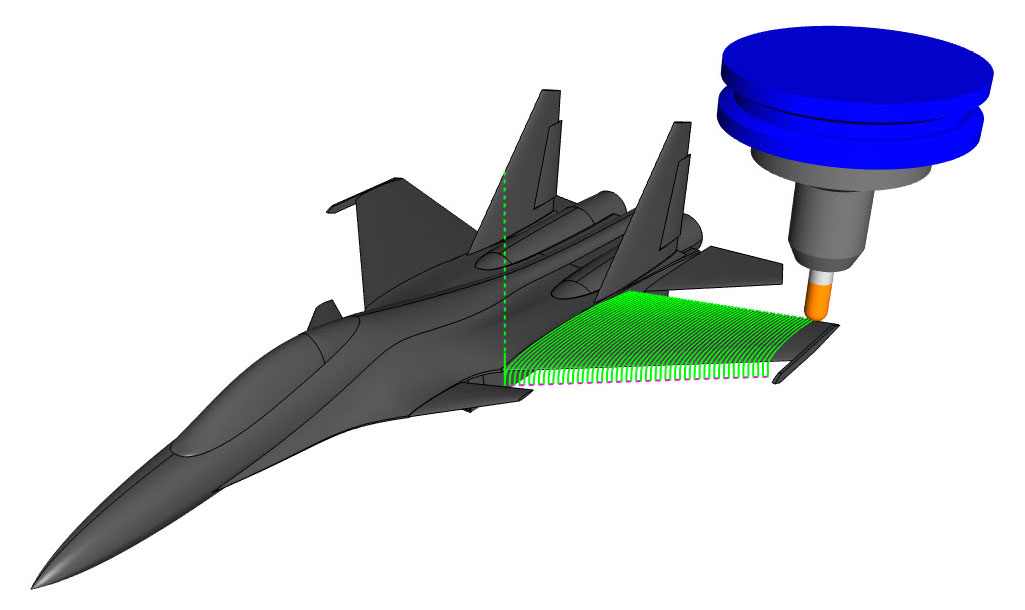
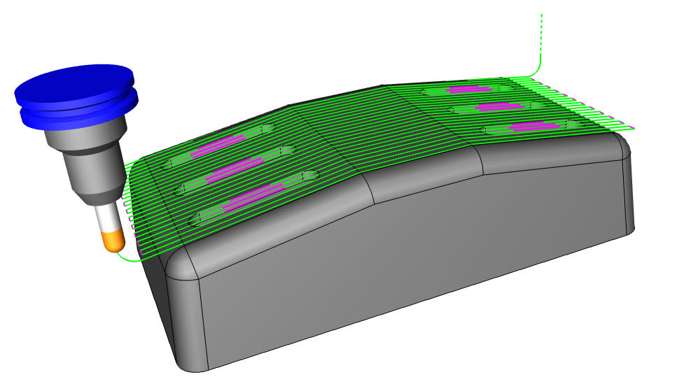
Parallel Cuts
The parallel cuts surface base toolpath is very similar to a planar or Z level finish strategy. What sets this toolpath apart is the control it gives you to handle gaps in your surfaces. “Not having to fill in surfaces that would otherwise cause the tool to drop down in cutting is a huge time saver,” says DePoalo. The Parallel Cuts feature creates a toolpath pattern with slices that are parallel to each other. The orientation of the slices are defined by two angles that include a machining angle in X-Y (which rotates the slices around the Z-axis) and a machining angle in Z. The geometry selection only requires a drive surface/surfaces.
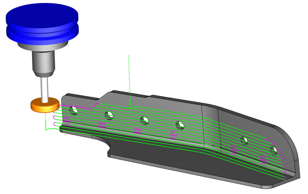
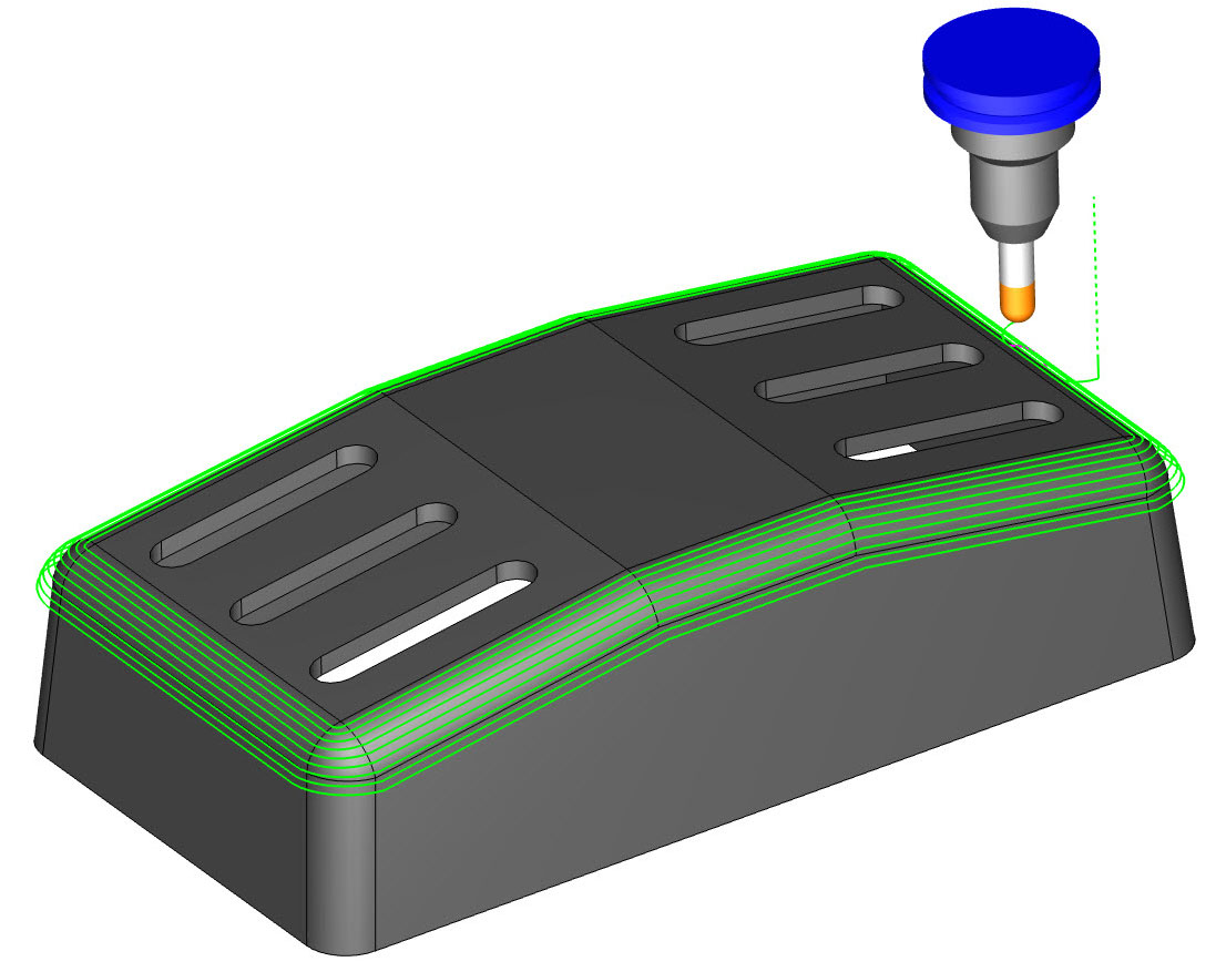
Cuts Along a Curve
The cuts along a curve feature allows you to create a toolpath that is perpendicular to a Lead curve (drive curve) on a selected drive surface. If the curve is a straight line, then the cuts are created parallel to each other. You can use a surface edge as the lead curve, or a curve that is on the surface. If the curve is not on the surface then it is projected onto the drive surface to create the toolpath.
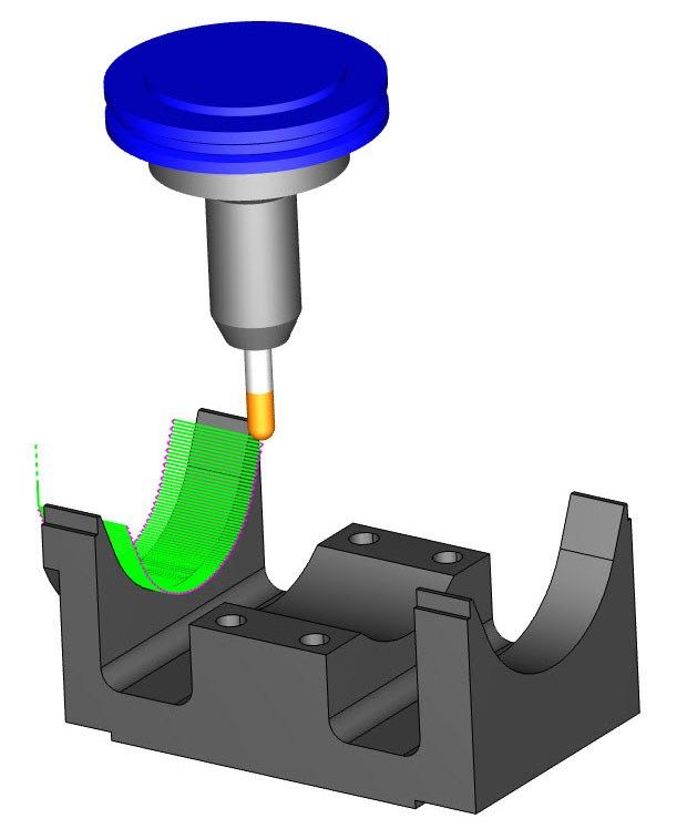
Morph Between 2 Curves
The morph between two curves feature creates a morph toolpath between two leading curves. Morph means that the generated toolpath gradually interpolates between the two curves and it is evenly spread over the surface. This option is very suitable to machine steep areas for mold making. When selecting the two curves, the geometry should be selected directly from the drive surfaces.
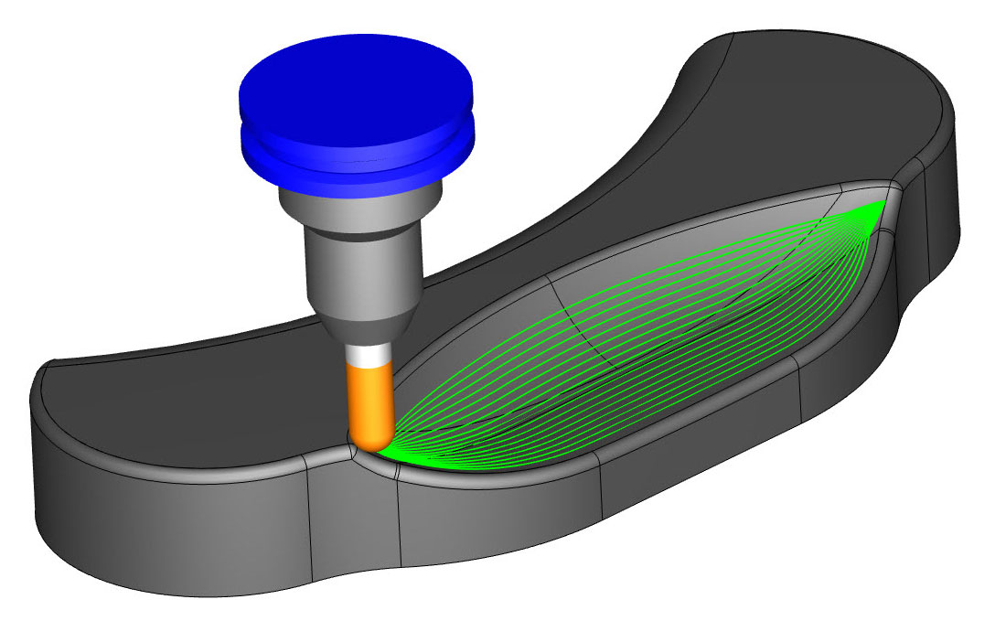
Morph Between 2 Surfaces
This cutting strategy works very similar to morph between to curves, the difference being your input geometry being 2 surfaces vs 2 curve boundaries. “Morph strategies are very popular because the cutting paths generated follow the flow of the surfaces,” says DePoalo. The morph between two surfaces feature creates a morph toolpath on the drive surface. The drive surface is enclosed by two check surfaces. Morph means that the generated toolpath is approximated between the check surfaces and evenly spread over the drive surface. This is great for impeller machining with twisted turbine blades but is also highly advantageous for 3D surfacing. The main advantage is the possibility to compensate the tool to the drive surface and check surface in the left and right corner of the work piece. This is accomplished using the tool radius which is the distance (margin) between the tool center and the surfaces.
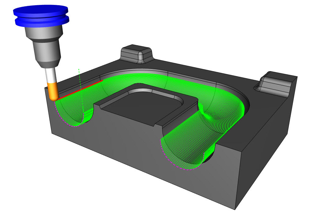
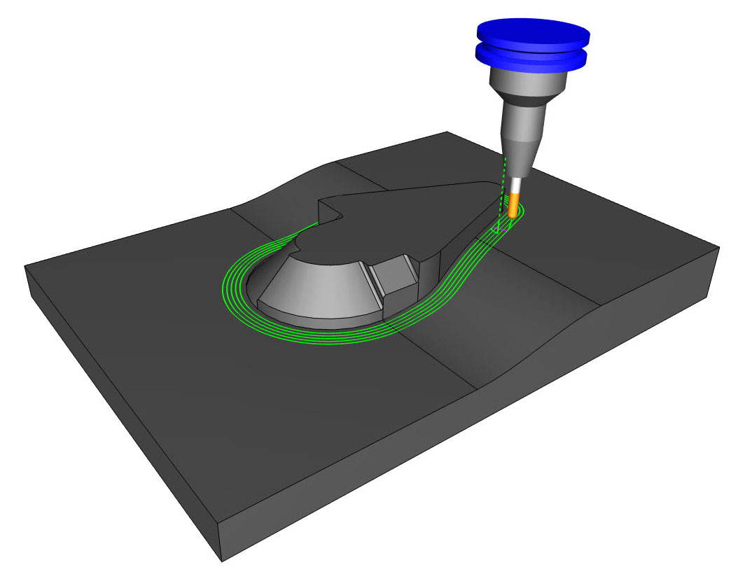
Parallel To Multiple Curves
The parallel to multiple curves feature creates toolpath segments parallel to a leading curve. The neighboring toolpath segments are parallel to each other. An important point here is that the cuts are not simply copied next to each other; every new cut is an offset of the previous cut. When selecting the curve geometry, select the curves directly from the part. When using a single drive surface, you can only select one curve from which to create a parallel toolpath. When using multiple drive surfaces, you can then select multiple curves to use. Each curve is only used for the drive surface nearest to that curve.
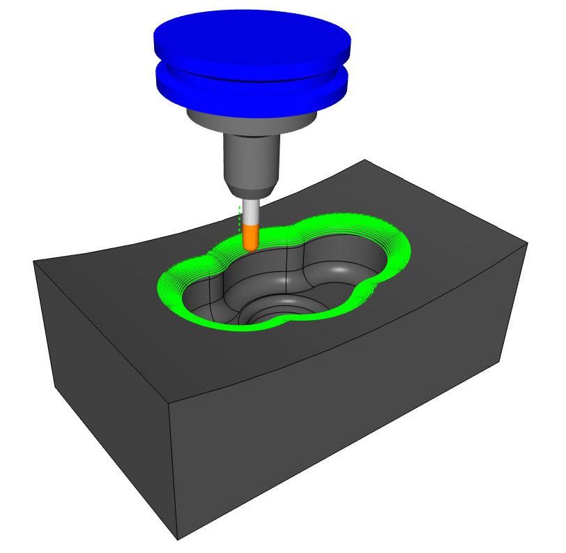
Project Curves
The project curves feature is used to create projected toolpaths using either a user-defined geometry curve, offsets of that curve, a radial pattern or a spiral pattern. When selecting curve geometry directly from a surface, the projected toolpath is identical to the original. When the curve geometry is above the surface there are multiple possible results depending on the scenario and parameter selections. This pattern can be used to create engravings as well as spiral or radial finishing patterns for complete surfaces.
Parallel to Surface
The parallel to surface feature creates cuts on a drive surface which is parallel to a leading surface. When selecting geometry, select the surface directly from the part. The advanced options for surface paths gives extended control over morph between 2 surfaces and Parallel to Surface. This option allows you to cut only in front of a selected surface. This toolpath is similar to an offset style path where you defined the curve(s) the toolpath is offset from. “Once of the advantages of using this strategy is the ability to machine surfaces that are going in many direction with a clean consistent path parallel to you drive curve. Unlike a morph routine that follows the UV lines of a surface, parallel allows to to create a machinable path on complex surfaces that otherwise would result in tool motion that is not conducive to cutting,” says DePoalo.
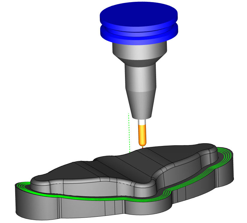
One of the huge benefits of this features is undercut machining. Being able to machine negative drafts using a t-cutter or lollipop is a common practice with this toolpath. Also, because the input geometry are surfaces it can make it easier for selection versus using its sister toolpath parallel to multiple curves. Advanced surface based machining strategies can reduce cycle times and help your shop produce superior part finishes on every 3D job you do.


Leave a Reply