The Purpose of CAD-CAM Software with CNC Machine Simulation
As CAD-CAM Software offers CNC businesses a wide variety of design and CNC programming benefits, the aspect of Simulation has steadily advanced over the past 10 years and has become a critical aspect of offline programming in an effort to provide the necessary utilities that help eliminate costly programming mistakes at the machine. Much of this is due to improvements in computer hardware, graphics capabilities and the fact that simulation in CAM software products has seen a lot of improvements coupled with the fact that simulation technology is now more accessible and more affordable than ever. So why should CNC businesses insist that they have machine simulation? Keep in mind that not all CAD-CAM products include or offer full machine simulation.
Here’s why you want CNC Machine Simulation for your CNC manufacturing shop:
- – Review the toolpaths of your program before physically machining the part.
- – The simulation functions will allow you to set machine travel limits and detect over travels.
- – The simulation will allow you to check for any errors on the part, including machine, tool and tool holder collisions.
- – CNC Machine simulation that allows you to utilize your machines Kinematics is going to allow you to visually see your machine tool in action.
- – You can see exactly how the finished part will look cut on your machine in a virtual environment.
- – Full CNC Machine Simulation allows you to set up an unlimited amount of machines that are accurate to the machines in your shop.
- – The simulated machine can be turned on and off or made transparent in the simulation process for close part inspection.
- – You can calculate machine cycle times on part programs.
- – You can use dynamic viewing functionality which helps in the inspection process.
- – CNC Machine-Part Deviation is available, showing you where tools were unable to machine within the associated operations.
These are just a few of the many benefits of CAD-CAM & Simulation technology. The biggest benefit is eliminated waste as you end up no longer scrapping parts due to programming errors. It really is about having piece of mind.
CAD-CAM Machined Part Deviation
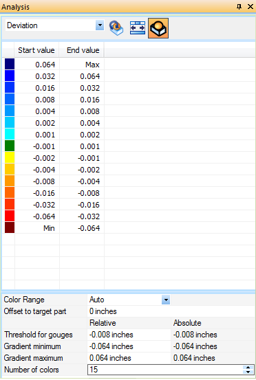 This utility is like a diagnostic tool that allows a user to define tolerance ranges for part deviation and display them on the cut model. The simulation analysis exists for the user to define colors to various deviation tolerances. This functionality is a great way to see exactly where left-over material will be not only for milling toolpaths but for drilling operations as well.
As the toolpath is simulated these colors are made visible representing deviations as well listing them in the deviation analysis tab. This tab is customizable by the user. This type of analysis helps the programmer to determine surface finishes and also to find areas where stock may be remaining due to a tool being too large to fit in an area. Using this powerful feature to eliminate guesswork can allow programmers work more efficiently and with confidence.
Multi-Tolerance Deviation Analysis Simulation is where all of the changes in tolerance are displayed during simulation for analysis.
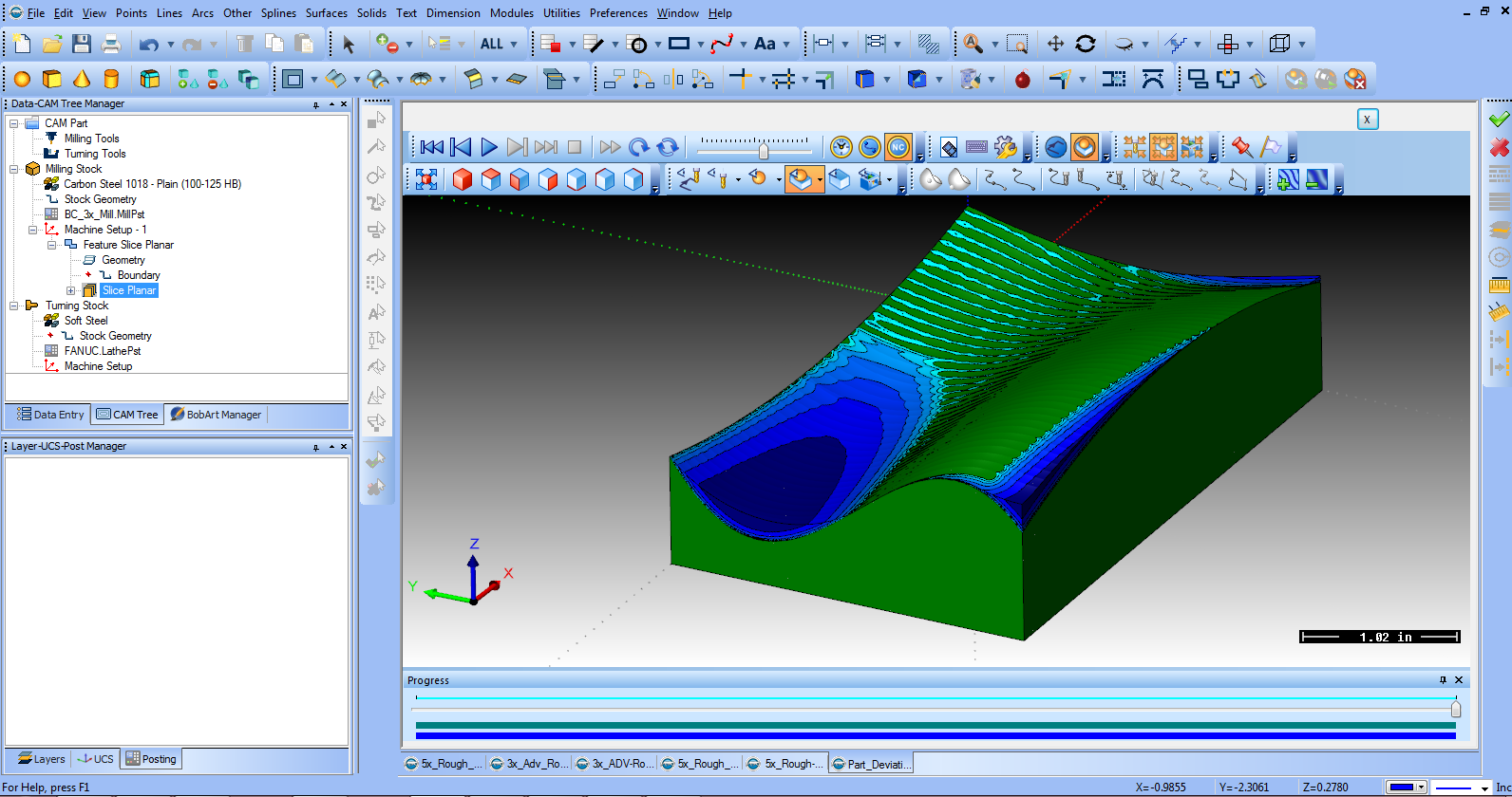 Here you can see the variations represented in green and blues. Once again deviation tolerances can be set to different colors for easy visualization.
Part Deviation Analysis will show you where a cutting tool did not go before you actually run the program on the CNC machine.
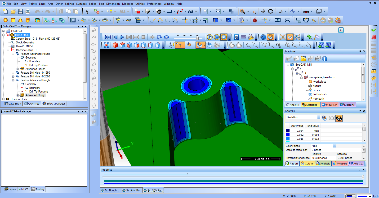 This can help in a number of ways: properly selecting and setting up toolpath finishing operations, addressing the tools you are using for the program, and more. A programmer can easily see where the deviations are in the program, the operation and which tool was in use by the program. This is all very valuable data as all operations are inspected by the operator. Have you ever wanted to know more about what tools to use in a program?
Advanced CAD-CAM CNC Machine Simulation
Machine Simulation allows you to use your machines Kinematics to simulate the actual machines motion as well as the toolpath operations and more. Machine creation starts with a machine definition to define each element of the machine, such as the linear and rotary axes. Then the parameters are defined for each element of the machine, such as the moving direction and limits. The parameter values defined in the Machine Definition are used to create posted NC programs. For each element, geometry (.stl) files are added to define what appears in the simulation window.
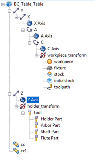
Notice the structure of the machine tree and the machine elements. When building a machine, you must examine how the machine is built. For any machine configuration, you can think of the machine as having a base. The base is the foundation upon which the machine is built. Every machine element is attached to the base or to some other machine element. The relationship of all of the machine elements, how they are connected, and in which way they move, defines how the machine is built.
Once the data is input into the software, the machine simulation is possibly giving the operator everything he or she would need to fully view the CNC machine tool in action.
In BobCAD-CAM CNC Software the machine simulation also includes what are known as “Dynamic Elements.”
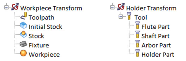
The dynamic elements are the elements that can change with each NC program. The Workpiece Transform contains the first set of dynamic elements in the tree. This transform includes the toopath, initial stock, stock, fixture, and the workpiece. Generally, you do not have to define geometry for each of these items because they are defined by each program that you create. This is also true for the Holder Transform elements. These dynamic elements are automatically created in the tree for you when you create a new machine (except when using User Defined) in BobCAD-CAM CNC Software. Also in the BobCAD-CAM software PRO version Machine Simulation the geometry for the holder element in simulation is automatically defined using the assigned tool holder from the milling wizards.
These features are easy to set up and use.
Machine simulation provides dynamic viewing features. By changing the CNC Machine Housing view you can see the machine tool in different modes.
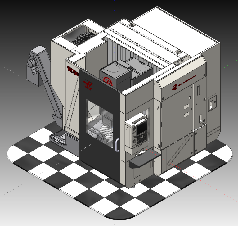
Solid
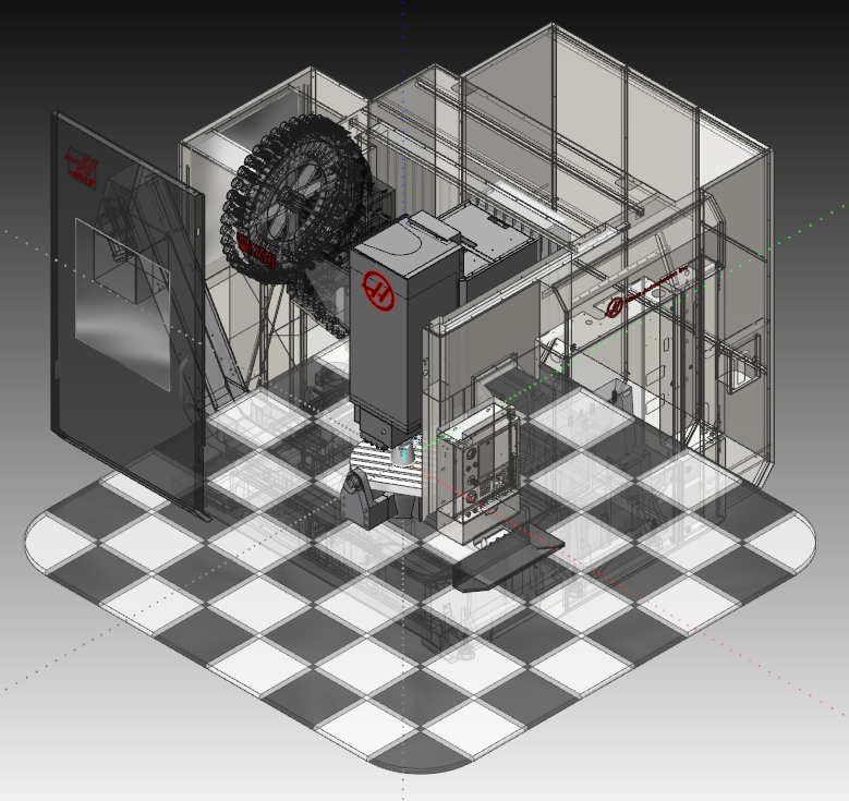
Translucent & Off/Hide
Simulation can take place in any view required by the operator so that everything can be analyzed.
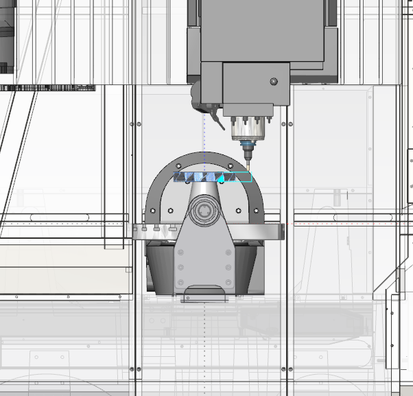
In the end, the Machine Simulation features provide a vast amount of information for the operator before the program is run on the CNC machine tool.
Click here to download this free white paper.
Download a free CAD-CAM demo with simulation HERE
For more information on implementing CAD-CAM software with machine simulation into your CNC machining business call us at 877-262-2231 or 727-442-3554.


Leave a Reply