CAD-CAM, Computer Aided Design and Computer Aided Manufacturing, software is used for designing and programming automated CNC cutting toolpaths to manufacture parts. 3D geometry and solid models are designed in or imported into the CAD-CAM software and programmed using a series of 3D cutting operations, each with their own set of specific parameters that perform roughing, semi-finishing, and finishing operations. If you have and use a CNC machine to make parts you should know what is available within CAD-CAM. Here you go…
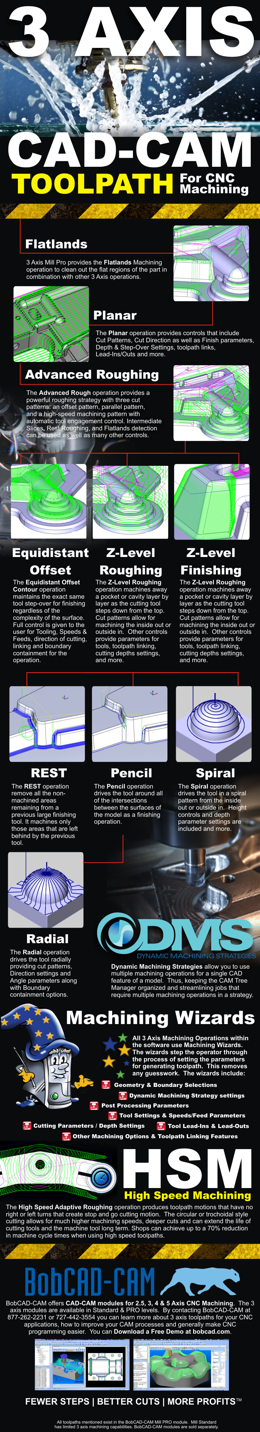
3 Axis toolpath Strategies and Operations
3 Axis CAD-CAM machining operations are the primary focus of any 3D machining job that requires 3D surfaces to be machined. Manufacturers want a CAD-CAM system that draws on your full computing power to deliver efficient and fully optimized toolpaths for complex jobs at the CNC machine. In addition, the BobCAD-CAM software takes advantage of multi-core hardware processors to speed up the mathematical toolpath calculations and reduce the amount of time it takes to generate 3D toolpaths. The CAD-CAM “ARC fit” feature uses arc segments in combination with line segments to generate toolpaths which significantly reduces the volume of NC code that a 3D program typically has and aids in producing a smoother finish in high tolerance tool step over situations.
More and more 3D parts are being designed as CAD design technology evolves. An increased variety of part types require advanced CNC machine toolpaths for programming in 3 axis. Therefore, 3 axis CAD-CAM is needed to streamline CNC programming and simplify the steps necessary to rough and finish complex 3D parts in a CNC milling environment.
The following info-graphic outlines the 3 Axis toolpath operations that are offered with the BobCAD-CAM Mill Professional CAD-CAM software.
Dynamic Machining Strategies™

Dynamic Machining Strategies™ (DMS™) in BobCAD-CAM allows the operator to apply any number of machining operations to a single CAD model feature in addition to allowing on-the-fly edits of these operations. This is where the user has the ability to load a single or multiple machining operations to a single strategy “template.” DMS™ is best used within a machining wizard, which stores the data and uses it to create toolpaths.
DMS™ functionality is developed into existing machining wizards within the CNC software to remove the guesswork as to where the user is in the process and how to properly input the data for each machining strategy without missing critical details. This provides maximum efficiency in the programming workflow.
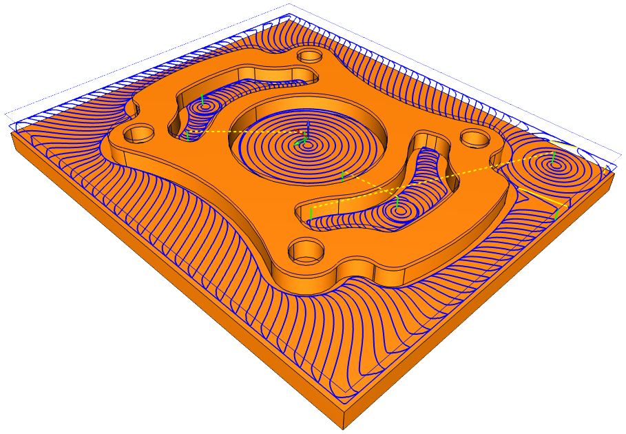
High Speed Adaptive Roughing
High-speed adaptive roughing toolpaths provide significant advantages for CNC machining. It’s pretty fair to say that most shops are cutting faster today than they did ten years ago. Albert Einstein said it first and best, “All motion is relative.” From that perspective, incremental improvements in rate mean that a shop is machining at high speeds compared to what they were able to do previously. Increasing the feed rate of a ball-nose end mill in tool steel from 12 to 24 ipm and spindle speed from 4000 to 8000 rpm is a 100% increase in cutting speed and well within the capabilities generally found on most CNC machine centers.
 As the cutter creates a chip, the heat generated by that action is transferred to the chip. When the chip breaks and leaves the cutting zone, the heat is carried away with it. A big advantage of high speed machining is that elevated rates of speed and feed, the chip is cut and evacuated so fast that it tends to transfer little or no heat to the work piece. In many cases this eliminates the need for coolant. At conventional machining speeds, there is time for heat to move from the chip to the uncut metal and create a work-hardening condition.
A harder material increases the force needed to create a chip, which in turn creates more heat and the cycle continues like this. Coolant mitigates the cycle by reducing the temperature in the cut zone and flushes away hot chips. However, at very high rpms, the tool rotation throws coolant away from the cut zone so unless you’re using very high pressure or through-the-tool piping, it never reaches the cutting zone to do its job. Another factor to consider is trapped chips that can remain in the cut; which means they may be re-cut by the tool. An air blaster is a very efficient tool for evacuating chips in high-speed applications.
BobCAD-CAM’s high speed adaptive roughing can significantly help a shop manufacture more accurate parts with better surface finishes, faster, and more profitably. Often times, because a machine tool and work piece setup has to be very rigid for high speed machining, the results are more consistent. All of these together amount to higher efficiency in CNC programs and machining, which typically results in higher profits for a CNC business.
For over 30 years, BobCAD-CAM has provided CAD-CAM CNC software products to the global manufacturing industry. The software can be found to increase CNC productivity for many applications including educational and independent home hobby use. BobCAD-CAM also provides a variety of quality training products that include regional and online training classes or private sessions tailored to specific applications.
CLICK HERE to secure a free 3 axis CAD-CAM trial today!
Contact BobCAD-CAM at 877-262-2231 or 727-442-3554 to learn more.
Other related CAD-CAM articles that you may be interested in:


PRICING ON 3 AXIS MILLING