CAD-CAM reduces CNC programming complexity. One of the challenges that machine shops face when it comes to 3 Axis milling has been in the area of 3 Axis Z-Level milling. This is also known as “waterline” and “Core milling” as well as Z-Level Roughing in the world of CNC part programming. When leaving the world of 2.5 axis milling and entering the world of complex 3 axis surface machining, a new set of particular skills are required for generating an accurate and efficient NC program.
 Without CAD-CAM these types of cnc jobs can be nearly impossible due to the math calculations involved. With this being the case, modern cnc software products provide a variety of 3D machining capabilities that continue to give programmers faster, smarter and easier solutions to machining difficult 3D parts. The Z-Level Roughing operations are generally used as a way to remove the majority of the material necessary to perform a semi-finish roughing operation with a smaller tool that has a reduced step over and Z step-down during cutting. These operations are very popular before using a finishing type toolpath operation that will produce a clean surface finish for the part.
Subscribe to BobCAD-CAM's CNC Software Blog
Join your fellow manufacturers! Get BobCAD-CAM’s latest CAD-CAM articles straight to your inbox. Enter your email below:5 Ways CAD-CAM Improves Advanced 3 Axis Roughing
There are certain benefits in CAD-CAM software that you should look for in order to take full advantage of the latest in 3 Axis CNC programming technology for your shop.
They are:
CAD-CAM software developed to support duel-core processors. Multi-threaded toolpaths are important as calculation times are hugely reduced when the CAD-CAM software supports hardware with duel-core processors. It could mean the difference of clicking the “calculate” button and going home for the day versus clicking the calculate button and having your toolpath calculate within minutes.
CAD-CAM software that provides roughing “Step-Reduction” functionality. 3 Axis roughing operations can leave a large stair-step type finish after machining that will require a second machining operation to reduce the left over material before finishing. Using CAD-CAM that offers functionality for “Intermediate Steps” or added forced steps in cutting is important. Equally important is the transition from one tool and step over to another along with the characteristics of how such a machining operating operation performs. Creating an efficient program is the main objective. It isn’t always necessary to perform a tool change from one set of cut-paths to another.
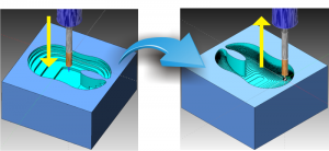
Step reduction functionality allows you to machine the bulk of material from the top down and then machine back up the walls of the part removing the remaining material in specified equal intervals. You could call this, “Automatic Step reduction.” The benefit is efficiency, whereas this type of functionality makes the most out of the program and reduces the amount of finishing time while supporting tool life.
CAD-CAM that provides High Speed Advanced Roughing. Traditional Z-Level roughing toolpaths can be hard on tools and even though advanced step-reduction functionality may exist, high speed machining technology can consolidate the benefits of step reduction while greatly reducing machine cycle times. Not to mention that high speed toolpath benefits also include extending tool life due to a constant cutting engagement and increased cutter step-over advantages. Basically, using more of the tool at higher cutting speeds. The nature of this toolpath is to use more circular machining movements rather than traditional right and left turn movements. BobCAD-CAM software is currently the only CAD-CAM product in the world that offers this level of advanced Adaptive High Speed roughing technology for 2, 3, 4 and full 5 Axis CNC Milling.
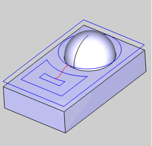 Advanced roughing toolpath operations for complex parts should also include toolpath “Linking” options. This is the methods that a tool will take when moving from one toolpath to another. Your part may require a retract from one cut to another, a direct move from one toolpath to another or a “S” type high speed link from one cut to the next. The S-Link creates an S shape link between each path in the toolpath tangent to both paths that lie on the surface of the model.
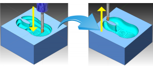
CAD-CAM that provides REST operations. Advanced roughing operations will leave material behind where the larger tool could not machine. CAD-CAM software should allow you to take the previous tool data and generate toolpath for the next smaller cutter based off of the previous operation and allow you to machine the rest. This operation will save you time due to the pure automation value and recognizing leftover material that needs machining.
CAD-CAM that optimizes the toolpath and uses ARC segments wherever possible rather than line segments. Generally toolpath in CAM is created using tiny line segments that will result in individual lines of g-code in the output program. When possible you may want to use arc segments through a feature called, “ARC Fit” that will use arcs instead of lines for the toolpath. This has value in the cleanliness of the machine path as well as the size of the g-code program that your machine will need.
By using this option you can greatly reduce the size of the program and produce improved toolpath results. These are some of the attributes you should review when implementing CAD-CAM software into your business for 3D machining. Each of them adds efficiency to offline program and gets you one step closer to better parts finished faster.
How Advanced Roughing Step Reduction Works
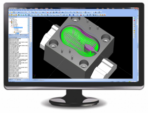
As discussed in earlier papers, CAM software should provide the operator with a Job Tree Manager which is the central command of creating toolpath and NC programs. The Job Tree is where you will perform job setup tasks, select tools, materials, create the stock and access all of the machine operations that the program would offer.
BobCAD-CAM software offers this type of scenario where a Job Tree is used for all of the above including post processing configurations, cutting conditions, machine setup options, indexing operations and more. By choosing “Mill 3 Axis”, the 3 Axis Wizard will open providing options for all 3 axis machining operations.
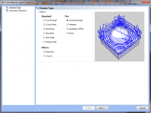 A machining Wizard is a series of dialog boxes that step an operator through all actions/stages associated with a machining operation. This is a huge benefit to new users as they literally remove the guesswork from programming. Advanced users also appreciate the wizards as they provide a large amount of flexibility in creating a program as there are a lot of options and override opportunities that make experienced users feel totally in control.
Use CAD-CAM software that provides machining wizards.
The stages of the advanced roughing wizard include:
• Rapid Movement Settings. These input fields will include the Clearance Plane, Rapid plane, Feed Plane and the Top of Part.
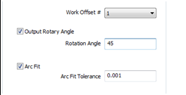
• Posting options. Most CAD-CAM software will allow the operator to add an index system to the job for 4th axis indexing. The index system will allow the operator to include machining operations. If this is the case, the wizard allows the operator to input the output rotary angle for the selected machining operation. This stage of the wizard should also offer the ability to use an ARC Fit option. This is where the operator can input an arc tolerance value which will be used when the software uses arc segments wherever it can in the toolpath. Once again, this will improve the quality of the toolpath and reduce the number of lines of g-code.
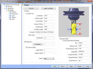
• Tool Data. The next phase of the wizard will give the operator access to the tool library, tool crib library, tool holders, feed and speed setting and override options as well as height and diameter offset fields and coolant options for the tool being used. The CAM software will automatically supply tool speeds and feeds based off of the material, operation and the size and type of tool that is being used. The selected operation will dictate the tools that are automatically inserted into the program. However the operator always has full controll over the tools that will be used in creating the program.
 • Machining Patterns and Cutting Direction. Depending on the operation there will be styles of machining patterns that can be used. In BobCAD-CAM Mill PRO software the Advanced Roughing strategy offers three different patterns, one of which is the new high speed adaptive roughing. Climb & conventional milling options are available as well.
• Parameter Settings. BobCAD-CAM provides the operator with Depth and Step Over options. This includes an “Intermediate Steps” option and the number of intermediate steps the user wishes to use.
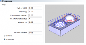
This is the phase of the wizard that gives you “step-reduction” benefits. The operator simply inputs the number of intermediate steps which creates forced cuts at even depths. In addition to this, another unique option is the ability to define what the top and bottom of the job will be. This allows the operator to control machining within the Z axis of the part.
These options and others give the operator solutions to machining in a variety of scenarios while providing total control.
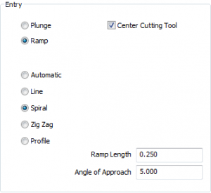
• Leads. There has to be options for the tool leads. Common options are Plunge, center cutting tool and Ramping options. Along with Ramping will be settings that should provide further control for using a linear ramp, spiral ramp, zig-zag style or a profile type ramp option. The lengths of ramp type and angle of approach is also important depending on the style of ramping that is chosen.
 • Special options for REST machining, Flatlands machining and how the operator would like to process the part for depth and region machining (By area or By level) among other options. Depending on the step-over and tool diameter there can sometimes be pegs left standing in corner areas where the toolpath takes a left or right turn. Among special options is the setting to remove these potential pegs by extending the toolpath slightly outward and back inward in these corners. It’s these types of options that can be useful when using advanced roughing toolpaths.
• Toolpath linking options. Toolpath that is for machining along the part at the same Z level has links between cuts. Direct, s-links or a retract type link can be used depending on the part and how the operator wishes to output the toolpath and program.
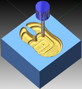
Once the operator has completed the process of setting up the operation with the wizard they would simply click a “Compute” button and the BobCAD-CAM software would automatically create the toolpath and load everything into the CAM Job Tree.
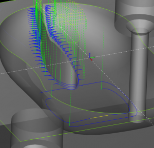
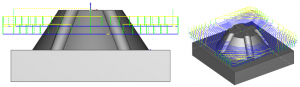
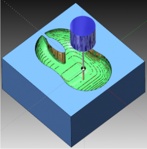
The advanced roughing toolpath would first machine everything from the top down based off of the input parameters and then start back upward from the bottom performing the intermediate cuts along the outer walls of the surface or cavity, reducing the large stair type effect that normal roughing can cause and leaving behind a much smoother and easier surface for the finishing toolpath to machine.
Advanced Roughing Simulation & Deviation Analysis
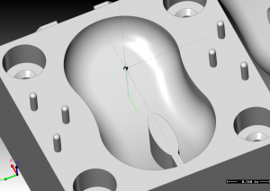
CAD-CAM should have simulation capabilities so that the operator can visually inspect the operations. Complex part programs will most likely have several machining strategies that makes the job. Each of these can be analyzed through simulation including a part deviation analysis, machine cycle time calculation and much more.
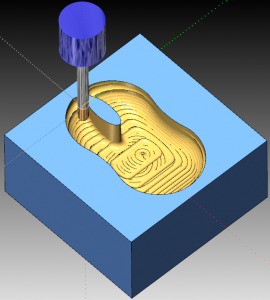
Advanced Roughing Down in Z Axis
Advanced Roughing Intermediate Steps
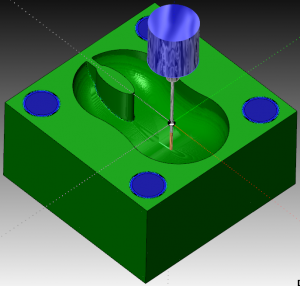
Finishing Toolpath
Simulation Part Deviation Analysis
The Simulated Toolpath Program
NOTE: All of the information in this article is available as functionality in BobCAD-CAM Software. The Advanced Roughing, REST, High Speed Adaptive Roughing and advanced Machine Simulation are available in the Mill 3 Axis PRO version of the software.
BobCAD-CAM has provided CAD-CAM CNC Software products to the global manufacturing industry for over 30 years. BobCAD-CAM software can be found to increase CNC productivity for many applications in aerospace, automotive, production manufacturing, mold making, general machining, woodworking as well as the medical manufacturing industry, consumer products, musical instruments, custom fabrication, defense industry and many others due to the products ability to automatically generate NC programming code for such a wide variety of CNC controllers. BobCAD-CAM software is also found in educational institutions throughout the world as well as independent hobby home use. Products include machining technology for 2, 3, 4 & 5 Axis CNC Milling, Routing, WaterJet, Plasma and Laser machines as well as 2 Axis CNC Lathe. BobCAD-CAM is modular allowing shops to start off at a reduced technology level and add technology as it is needed including add-ons for artistic machining and nesting sheet optimization. Unique technology includes adaptive high speed machining multiaxis milling and routing which is a first in the world of CAD-CAM software. BobCAD-CAM also provides a variety of quality training products that include regional and online training classes or private sessions tailored to specific applications. Professional certification and multi-tiered support solutions are available. Contact BobCAD-CAM directly for more information at 877-262-2231 or 727-442-3554.
Try a Free Demo HERE


Leave a Reply