by Chris Corbell
How Does CAD/CAM Software Improve CNC Lathe Programming?
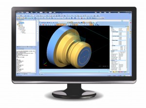
CAD-CAM software makes programming cnc machines faster, smarter and easier allowing cnc businesses to stay lean and competitive. When it comes to CNC Turning, CAD/CAM software can help increase process efficiency in a variety of ways:
 – Open the door to design innovation and long distant client collaboration.
- – Use existing designed part files for creating machine toolpath and NC programs.
- – Automate the programming phase and allow you to get away from conversational programming at the machine.
- – Save you time and money.
- – Allow for complete machine toolpath visualization prior to reaching the CNC machine tool.
- – Speed up cnc production by as much as 50%.

Gone are the days of having to spend hours calculating geometry by hand and writing NC programs with text editors. What used to take hours, sometimes days, now takes a matter of seconds when it comes to cnc machine toolpath and g-code programming. CAD/CAM software is the ultimate solution to streamlining productivity for cnc turning. It has a lot to do with time and potential loss of profit due to scrapped parts or other programming errors. The real question is how much is it costing you to not have a CAD-CAM product?
CNC Programming Workflow
So how does CAD/CAM software improve production workflow? First we have to dissect each stage of making a perfectly finished part with a computer aided design and manufacturing software product.
- –
 Imported CAD Part Files & Drawn OD/ID Geometry
 - – Stock Definition
- – Turning Tools, Holder & Insert Data
- – Material Database selection
- – Machine Post Processor Configuration & Machine Parameter Setup
- – Machining Operations & Toolpath Generation
- – Simulation/Verification
- – NC Code Output/Post Processing
- – Communications & DNC
This is the general sequence of events taken in a fully associative CAD/CAM Job Tree in order to keep the job organized, provide all of the necessary functionality all in one relative easy to use interface, and successfully program a lathe part. Each of these steps involves inputting data, making selections, and computing toolpath, as well as the output g-code program after simulation. CAD/CAM addresses these stages by providing the automation vehicle to speed up the process.
Design & CAD Interoperability
 CAD/CAM software allows you to directly import a wide variety of geometry files from lathe wireframe OD or ID profiles in DXF format or solids type part modal files such as Parasolids, STL, IGES, STEP and many others. The idea is to provide the flexibility you need to stay connected to your clients when they have a completed part model that needs machining. Turning parts tend to be considerable more simple than 3, 4 or 5 Axis cnc mill type parts. Once the file is opened in the CAD/CAM product geometry can be verified, edited and used for the toolpath creation phase. Most, if not all of the quality CAD/CAM products in the industry today are wireframe, surface and solids based. They can deal directly with solid models as well as the extraction of edge profile geometry directly off of a solid model for toolpath.
In terms of design, all of the required drawing features should be readily available for the part to be created, opening the door to innovation. Today most CAD-CAM products are “Hybrid” based in nature. This means that the software can utilize wireframe geometry, surfaces or solids in any order necessary to complete a drawing. 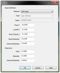 Design engineering products such as SolidWorks provide full assembly construction, motion analysis, stress analysis and so much more. These advanced features are highly beneficial in the design stage as products are being created for manufacturing and on to their respective markets. Once the part is ready to go the operator will typically set up the lathe stock through the CAM Job Tree Manager. This allows the operator to define the stock attributes for programming and visual display. Stock definitions will include the Material Type along with Z-Face and Cutoff data, the diameter as well as internal stock diameters and tool clearance data all in one. With the stock defined the operator can move on to setting up the tools, holder and insert data so that the software can properly make speed and feed calculations and more.
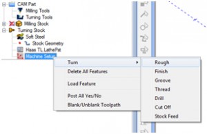
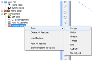
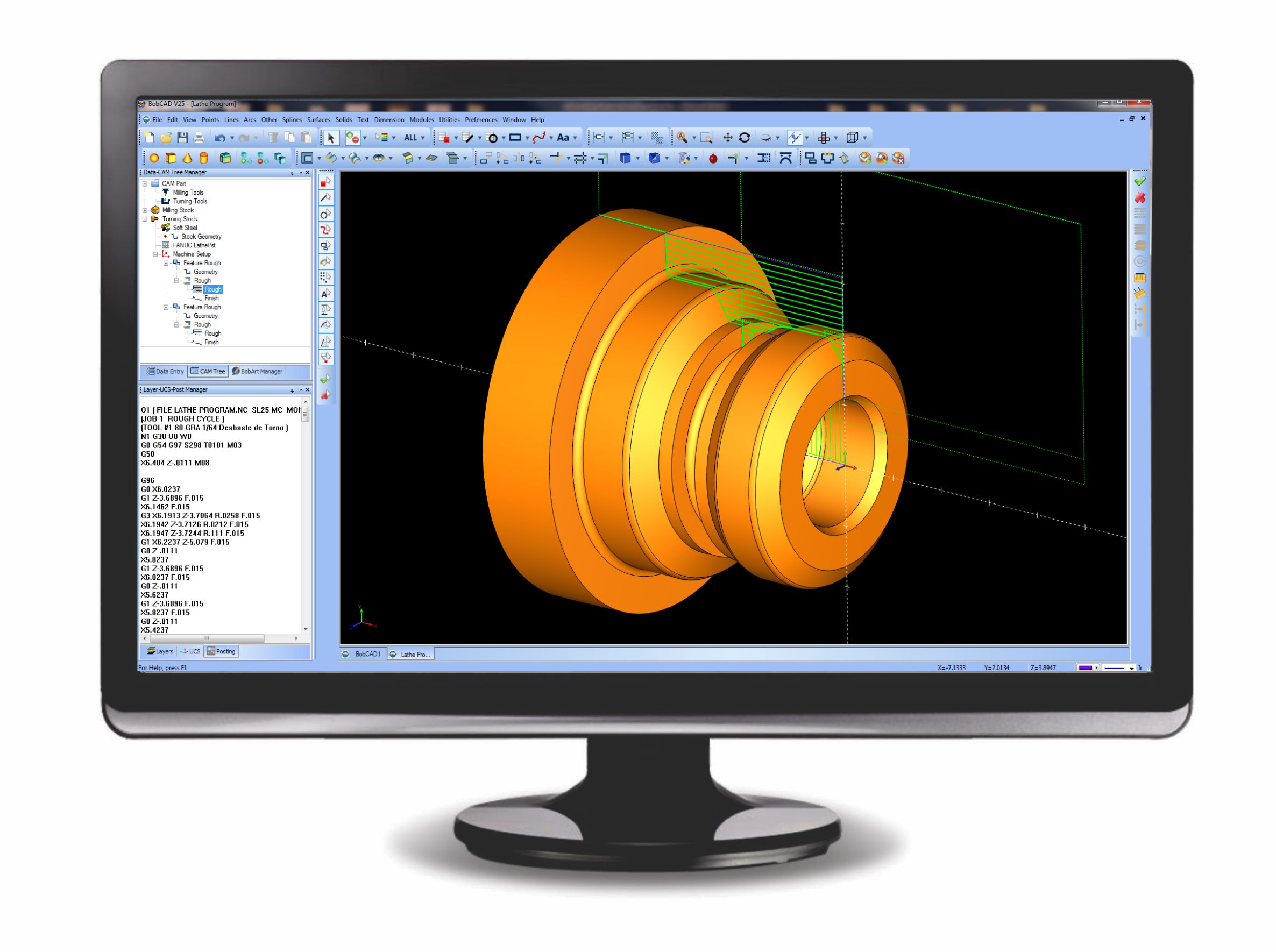
Lathe Machining Operations
All of the machining operations can be found in one location rather than scattered throughout the CAM interface. The Job Tree Manager organizes everything for speed. 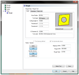 Once the tools and post processor configuration has been set for the machine tool, the operator can begin the toolpath creation phase of the process. Typical programming options for straight 2 Axis CNC Turing will be:
- – Roughing
- – Finishing
- – Grooving
- – Threading & Drilling
- – Cut Off & Stock Feed
These standard 2 axis lathe features can be made easily accessible within a CAD/CAM system for editing and toolpath creation. Each item should be its own series of dialog boxes that allow the programmer to edit and set up the operation. Take “Roughing” for example. Posting parameters can be set to post out separate moves in the output code or use canned cycles.
 The roughing cycle can be created with just a rough or a rough and finish combination. This can include a Face rough cycle or a Face Rough and Finish combination.
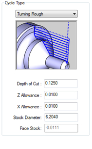 This is also the stage where the operator would tell the software what the roughing depth of cut will be, add any X or Z allowances, and make the stock diameter known, as well as set the face stock, as this data all affects the roughing code that will be output.
System and machine compensation options are some other options that can be controlled here by the operator. Tool exit rapid moves are also an important setting here and should have multiple options for rapid moves to the tool home position, the cycle start position or a pre-defined point. In some cases the operator may choose not to rapid to a location at the end of the toolpath. Lastly, the operator will need to input the information about the tool that will be used.
Based on the roughing cycle selections, information about the insert, insert orientation and machine information (offset register, turret position, Z & X Home Positions, etc.) are important at this stage for creating the program.
- –
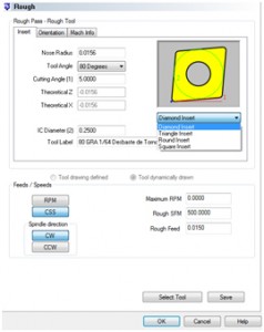 Nose Radius
 - – Tool Angle
- – Cutting angle
- – Insert Type
- – Feeds & Speeds Data

These are all taken into consideration and once the selections and inputs are complete, the programmer can click the OK button to save everything and move to the final stage of creating the toolpath. This is as simple as locating the roughing cycle in the Job-CAM Tree and computing the toolpath.
A tool database is an important aspect of CAD/CAM as it allows the operator to store all of the tool information for the parts that they machine. The toolpath results should be instantly created and displayed on the part in the viewing window for inspection.
 Each part will have more than one machining operation. The CAD/CAM software will generally allow the operator to blank and un-blank toolpaths as work is done to create each cycle to help visually. Once the program is complete, all of the toolpaths can be viewed. Any modifications to the part file that may take place at this point are ok as the software is fully associative, meaning that the toolpath can be updated without having to recreate a new job depending on the extent of the modification.
Machining operations that are in the job tree can also be moved around and new operations added as necessary without having to recreate an entire job. Operations can also be saved and used later on as needed through a “Save & Load” feature. These are just some of the many benefits to using a CAD/CAM Job Tree Manager to build machining programs.
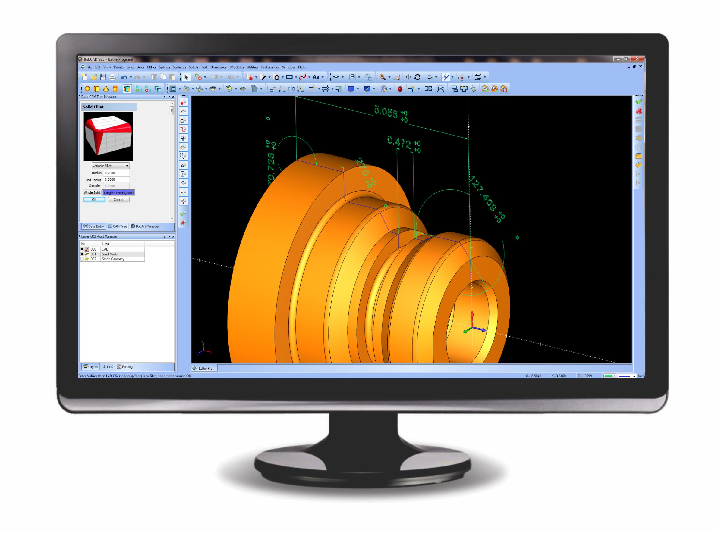
Simulation & Toolpath Inspection
CAD/CAM software should provide powerful simulation features allowing the operator to visually see what will happen during the cutting process.
 All of the information that was input by the operator to generate the toolpath is carried over into the simulation process. The simulation features provide a great number of benefits to the operator including information on:
- – Toolpath movements
- – Cutting Speeds & Feed Rates
- – Operation Data
- – Machining Sequence Data
- – Machined Part/Deviation Analysis
- – Cycle Time Calculations
- – Program Errors, Gouges & Collisions
These are just a few of the valuable features that come with simulation capabilities. A programmer uses the simulation features to check all of the toolpaths and machining operations before sending the NC program to the machine tool. Typically, simulation can be controlled by a standard toolbar that offers Play, Pause, Stop, and other controls.
![]()
More advanced simulation modules offer full “Machine Simulation” capabilities. This means that by using your machine kinematics you can simulate the full movements of the machine itself for an even more realistic visual of the actual machining process.
Post Processing & NC Code Output
A CAD/CAM system without full post processing capabilities is somewhat useless. All of the programming and toolpath creation is run through a posting engine or translator to generate the g-code program. The output NC code will have taken everything that the operator input into the CAM – Job Tree and “Post” it through a configuration file (Post Processor) that will create the exact language required at the controller. CAD/CAM software providers work hard with their customers and machine tool makers to create all of the different models that are out in the industry. Many machines have multiple controller models that all need to receive the g-code program specific to the controllers requirements. Generally Post Processor configuration files can also be edited and modified by the operator or by the providers’ technicians to be customized.
CAD/CAM software that has been configured for a CNC machine should not have to be hand-edited unless the operator wishes to make changes at the controller. Generally, once the post processor is set, everything is in order to begin sending the NC programs to the controller to machine the parts.

For more information on implementing CAD/CAM software for CNC Turning into your business call us at 877-262-2231 or 727-442-3554 or download a free trial version of our latest CAD/CAM software.


Leave a Reply