By Chris Corbell
Who said CAD/CAM was going to be easy?
CAD-CAM software can be a challenge to fully learn how to use for everything a CNC shop needs in order to program parts and output the correct g-code program efficiently. For as long as there has been CAD/CAM software, developers have faced the challenge of providing more and more functionality while continuing to keep these products easy to use. It hasn’t been easy. Ask any developer and they will tell you that the more features a CNC programming system has, the steeper the learning curves will be and the more technical support issues there will be. Yet without CAD/CAM, CNC shops simply cannot stay competitive and efficient.
Leave it to marketing to tell you their product will be easy to use. And even though it may be easier than another, there is still going to be a period of time where the operator will have to access training and spend time figuring things out in order to really take advantage of the power of modern CNC Software automation.
The General CAD/CAM Workflow
When you review the basic 2 or 3 Axis CAD/CAM programming workflow you will find that it goes something like this:
- Import the part file or complete the design.
- Create the material/stock for the job and origin.
- Create a Machine Setup or Work Offset.
- Setup the Material Type.
- Setup Cutting Conditions, Tool Patterns and any Machining Parameters that apply.
- Select the Post Processor Configuration.
- Start adding machining features, drilling, roughing and finishing toolpaths.
- Build the job in a CAM Tree Manager that allows you to edit the machining features.
- Compute and generate all toolpaths.
- Generate the G-Code Program.
- Simulation.
- RS 232 / DNC Send the program to the machine.
Looks fairly straight forward, doesn’t it? There is a lot of information that goes into the above list in order for CAD/CAM to really act smart and create efficient and effective programs for you. You have to input that information into the software. Otherwise you will often times get incorrect results and end up losing valuable time. So how has CAD/CAM been developed in order to keep it simple and make it so that nothing is left out?
The Success of Machining Wizards
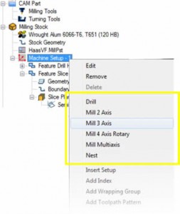
Wizards are used in software to properly set something up. In this case it includes a wizard for each drilling operation and all toolpath operations within the CAD/CAM system. In a CAD/CAM product the toolpath wizards should be easily accessible within a Job Tree – Manager so that the job remains organized.
Here you can see an organized location within the Job Tree where all of the toolpath options are listed.
Once a toolpath operation is selected the wizard will be launched to guide the operator through a proper sequence of steps for creating the toolpath. Let’s take a closer look at the benefits of a wizard.

The first benefit is having all of your toolpath operations defined and organized into 2 Axis, 3 Axis, 4 Axis and 5 Axis categories. The first step in the wizard would be to choose which operation to use. In the picture above we have selected “Pocketing.” By choosing a “Next” button the wizard advances to the next box which would be the geometry selection stage. This stage allows you to select the geometry that you will be using for the toolpath operation as well as any boundary geometry that the operator wants to use for containing toolpath. Some parts have several different areas per operation. By making the selections, the software can quickly optimize the machining sequence and knows where to apply the toolpath. In addition to this, the software should automatically detect the depth of the regions and use them later in the wizard. Once again, adding to the software intelligence and keeping things quick and easy for the operator.
The next phase of the wizard will allow the operator to adjust the Rapid Planes, Feed Planes and Top of part as well as any other options including the ability to select the top face of the part if the operator isn’t exactly sure of where it is, automatically adjusting the parameters.

Also notice in the above picture that the wizard provides a feature tree inside of the box. Advanced operators can jump to any section of the wizard just by clicking their mouse on the item in the tree. When finished with these settings, the “Next” button will advance the wizard to the next screen.

At this point the wizard will allow the operator to create an additional work offset if needed or a rotary angle if the program is for a 4th Axis. The “Next” button advances the screen.

Now the wizard is allowing the operator to choose and control all of the aspects of the roughing tool. The Tool Crib and Holder database is accessible, tool data as well as speeds and feeds data can be used or customized by the operator. Once the roughing tool details are input the “Next” button is selected to advance.
In the example we are using here, we chose a “pocketing” type machining strategy. Therefore, the next screen of the wizard will allow the operator the ability to create the type of pocket that is best for the job.

Here you can see that a high speed adaptive roughing type toolpath pattern was chosen for the job. The operator can also choose the cutting direction and other parameters for the pattern. By clicking the “Next” button the screen advances to the next phase of creating the pocket job.

Now the operator can input information for allowing there to be extra material for side allowance and/or a bottom allowance for a finishing tool as well as specific cutting depths for a single pass or multiple roughing passes. The benefit here is that all of the cutting depth information is located in one place along with the software ability to allow equal depths of cut or user definable depths of each cut.
As you can see thus far, the wizard is stepping the operator through the necessary process in order to create toolpath that meets the programmers specific requirements as well as optimizes the speeds and feeds based off of tools, materials and the input cutting conditions. Everything is in one place and is kept organized yet still allows the operator to customize important attributes of the program.
By clicking the “Next” button the screen advances to the next stage of the wizard.

This next screen offers the programmer/operator the ability to dictate what type of “lead-In & Lead-Out” they want for the cutter. These options will be different in some of the other toolpath operations. For example, the 3 Axis advanced options may give different styles.
The “Next” screen addresses the finishing tool.

Once again the finishing tool screen offers options which include Tool Crib, Tool Holder assignment, Tool Label, Offsets, System speeds and feeds or the ability to customize them and other important options. After the finishing tool data is set, by clicking the “Next” button the screen advances to the Finishing Tool Pattern screen. This screen provides the operator with Compensation options for the finishing toolpath.

The “Next” screen of the pocket wizard is the “Leads” screen that allows the operator the ability to choose lead-in and lead-out options for the finishing tool. They can be the same or different depending on the operators needs.

The last step of using the wizard is to click the “Finish” button or the “Compute” button. Because the CAM Job-Tree Manager has a feature to compute or generate all the jobs toolpaths at once, the operator can click “Finish” and move on. By clicking “Compute” the toolpath will instantly be created by the software taking everything the operator input into consideration.

Then the toolpath can be looked at in the viewing window.

You can see from this that the toolpath wizard is very thorough, allows a programmer to simply go through and set up the operation easily without having to worry about where everything is within the software. Another benefit is for new users as the software walks them through creating a program.
Other available wizards include the ones for all 3 Axis Milling.

4 Axis wizards include posting, tooling, paterns, parameters, tool lead-in and lead-out, toolpath linking options and more.

Even the advanced 5 Axis Machining Wizard has amazing benefits to complex programming that makes the process simple and understandable by even the newest programming members.

For more information on implementing powerful and affordable CAD/CAM software into your business call BobCAD-CAM, Inc. at 877-262-2231 or 727-442-3554. Download a free demo and look at the advantages BobCAD-CAM software can give you right from the box.


Leave a Reply