3D toolpaths can be challenging at first and knowing which one to use and why is something many people struggle with. The goal of this boot camp was to help shops get more out of their CAM software by showing how to use common 3D toolpaths and options.
Subscribe to BobCAD-CAM's CNC Software Blog
Join your fellow manufacturers! Get BobCAD-CAM’s latest CAD-CAM articles straight to your inbox. Enter your email below:Top 15 CAD-CAM Q & A’s From the Live Webinar
1) How to toggle shading on and off?
It’s common to want to turn shading of surfaces and solids on and off when developing toolpath. This allows you to see through your surfaces and solid to validate where toolpath is being created. The hot key for this is “S” on your keyboard.
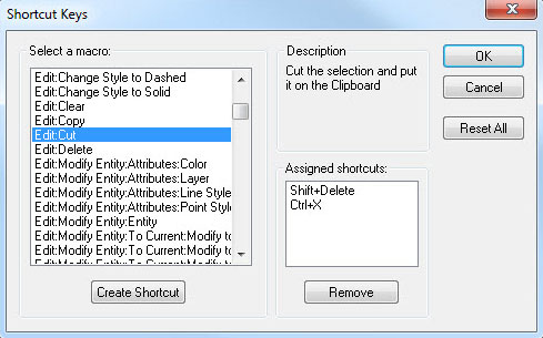
2) What are all the hot keys?
BobCAD-CAM does have hot keys / shortcut keys for common features. For the complete list of hot keys / shortcut keys go to preferences > shortcut keys. Here you will see all of the feature options and the assigned shortcuts.
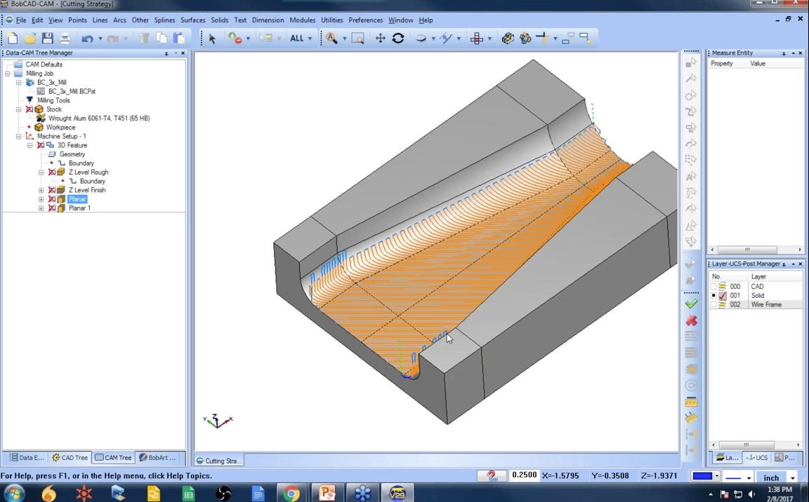
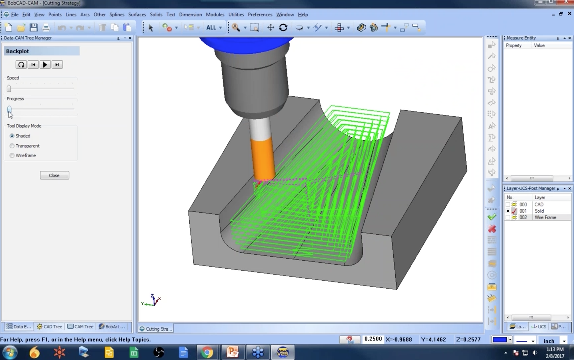
3) Why do you use planar?
Planar is a one of the most commonly used toolplaths for 3D machining. It works by moving back and forth over the surfaces and solids you’ve selected at a user-defined angle and stepover. It’s used for roughing, semi-finishing and finishing cycles on 3D parts.
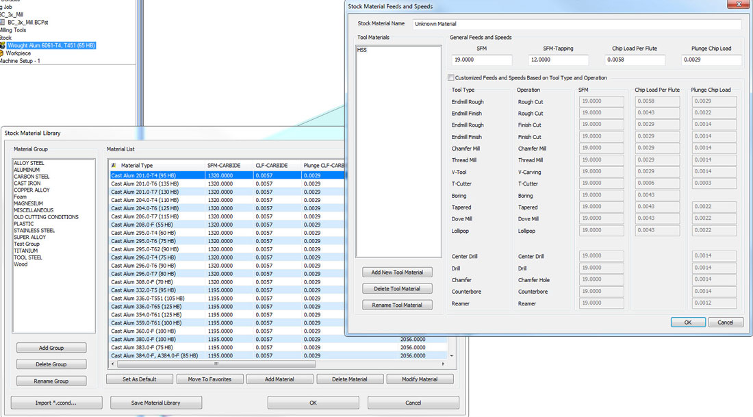
4) How do you set up speeds and feeds for other materials?
BobCAD-CAM does have a customizable material database that allows users to add additional materials, create material groups, set defaults, delete materials and modify materials. The material database is used to set SFM and chip load for the material, tool type and operation. The material database is one way to customize speeds and feeds for materials that are listed in the default database. Another, more popular way is to save machining features with predefined speeds and feeds. The benefit of saving machining features is what information is saved. Instead of just speeds and feeds, additional information is saved with the feature, like depth of cut, stock for finish, etc. Another option would be to default speeds and feeds for cutters. This is another popular option where users can create tools in the tool library with speeds and feeds for the material type the tool is used on.
5) Where can you save a feature to?
Saving features is one of the most productive tools that BobCAD-CAM offers. It allows you to save toolpath settings to be used on future projects. Features can be saved on your computer, network or external devices.
6) How do you control the machining order of operations?
If you right click on milling job and go to machining order, the machining order dialog box will come up. There you’ll find a list of all your operations and the order they will be posted in. You can optimize the cutting order by feature (the order features appear in the tree), by tool per setup (tool dominate posting), or tool (tool dominate across all setups). If you want to make a change in the cutting order, you can also move operations up and down in the list by selecting the operation and using the up and down arrows.

7) What do you set your rapid plane between moves and operations?
3D cutting features have 3 inputs that control the Z position of the tool between groups of geometry and at the start and end of the operation. This is your clearance value which you edit under your machine setup. Users can also define the rapid plane which is the Z position the tool goes to as it repositions. Users can also set up a feed plane which is how far above the cut the tool switches to feed move after it’s been repositioned to the next cut.
8) When do you use pocket in or out?
The pattern pocket in or out is used to control what direction the pattern cuts in. Pocket in starts on the outside and works its way in. Pocket out starts on the inside and works its way out. For inside work, I would use pocket out. For outside work, I would use pocket in.
9) How do boundaries affect your toolpath?
Boundaries are used to limit or contain where your toolpath will be generated. Boundaries allow users to control where the toolpath is created on the selected surfaces and solids.
10) How do you control a constant cusp height in BobCAD-CAM?
Most toolpaths offer a stepover value that is a relative XY value. What this means is, as the surface of the part changes in Z the stepover value does not accommodate for this. For a scallop based operation, BobCAD-CAM offers equidistant offset, which uses a stepover that is based on the surface area.
11) Does the center of the tool always go the boundary or do you have other options?
When using the standard toolpaths, yes, the tool center is driven to the boundary of the tool. Mill Pro packages offers boundary control for center, inside or outside.
12) Can you apply an allowance for all features or can you set an allowance for each operation?
Yes, for those features that have multiple operations you can use “apply to all operations”.
13) What options does BobCAD-CAM have to start the tool off the material?
The strategy and version you are running will determine the options available to you. In many cases, users will extend the drive surfaces start to the tool off the material.
14) How can you target a small area of a single surface to repair a damaged area of a part?
You would use a boundary to limit where the toolpath is cutting.
15) Where are the common part zero locations?
The part zero, also know as the origin or work offset, can be almost anywhere. It really depends on your setup and what is common in your shop. A standard location could be the top, back left corner of the part. In other scenarios, the zero may be the top center. So it’s really going to depend on your setup and experience.

Want to learn more about CAD-CAM software?
Sign up to receive alerts for upcoming webinars here.
Or contact us at 877-262-2231 or 727-442-3554.


Is posible to use an planar mill with 45 degrees for do a chamfer?
Hi Francisci – Yes, you can do that.
For #15, in machines that don’t use ATC and calibrated toolholders, the choice can sometimes come down to whether there will still be stock material to accurately touch-off the next bit for Z0. If the first bit’s toolpath and the second bit’s toolpath use the same machine setup origin, but there’s no longer any material left at that Z0 height, it makes it hard to correctly touch-off for that second bit. Or,worse, you might even have to remove the part and touch-off on a setup block ;-).
Thom – That is a great point and the main reason why many will choose to zero off a gauge block or a fixed location of the fixture / work holding. This way as material is removed it will not effect the touch off location.