What are check surfaces?
These are used to trim away unwanted toolpath or to bump toolpath up and out of the way.
What are boundaries?
These are used to limit toolpath, restricted by tool center, tool inside or tool outside.
Subscribe to BobCAD-CAM's CNC Software Blog
Join your fellow manufacturers! Get BobCAD-CAM’s latest CAD-CAM articles straight to your inbox. Enter your email below:1) Can you explain how to choose the “initial” milling point?
Depending on the toolpath operation – different options are available to control where the tool starts cutting from.
For example:
Advanced Planar
This toolpath offers you the choice of which side of the part you want to start cutting from.
Advanced Roughing
If you want to choose a start hole location, you can uncheck the center cutting tool option on the leads entry page. This allows the tool to start off the material or in a pilot hole (aka no plunging into the material). Now to choose the hole location(s) – in the CAM tree you’ll see a selection option for drill tip positions. This is where you select the pilot hole location.
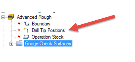
The reason it’s called “drill tip position” is because the point location you select is an X Y Z location, or in other words, how deep you drill the pilot hole.
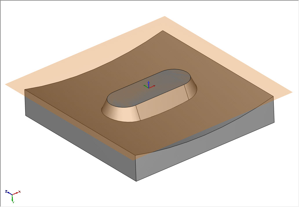
2) If I have a rectangle boundary at 7.75” square and another at 8” square, how would I mill between these boundaries?
For something like this, I would use Advanced Z Level Finish. This is a waterline toolpath that will follow the tapers of the walls. Just think of it as 2D profile, following the wall and stepping down.
You would select the inside and outside boundary to “contain” the toolpath between – just be sure to change the boundary default from center to inside to make sure other surfaces aren’t affected. This will do a great job of cleaning up between those 2 boundaries, while keeping the tool inside.
3) Why would you want to restrict your toolpath in 2D and 3D?
The main reason is to control where material is removed. Using a boundary or check surface gives the user the control to “contain” where toolpath is created and where it’s not.
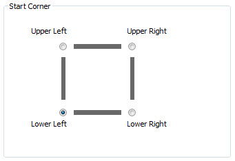
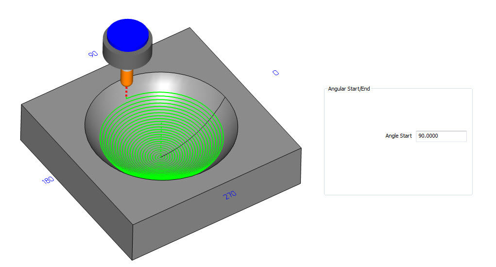
4) If I’m cutting a large round bowl cavity and want the cutter to spiral in, how can I control the location of the spiral?
When working with the spiral toolpath, you can choose to start in the center or on the outside. You can also control the start location using the Angular Start/End. 90 degrees would be the 12:00 location on a clock face.
5) Why does the extract edges create geometry based on the UCS (User Coordinate System) and not the machine setup?
When you create geometry, it’s based on the UCS you’ve selected. The machine setup location does not determine where geometry is created. What you can do is create a UCS for your machine setup location – this way your machining and drawing will be based on the sample orientation.
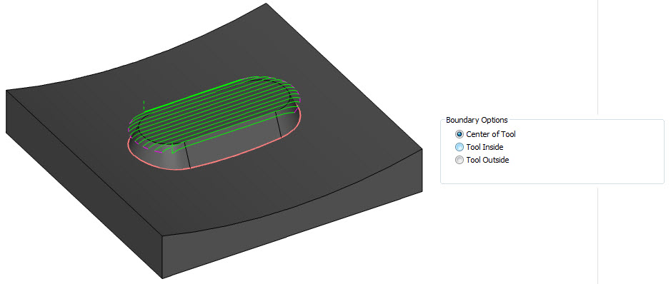
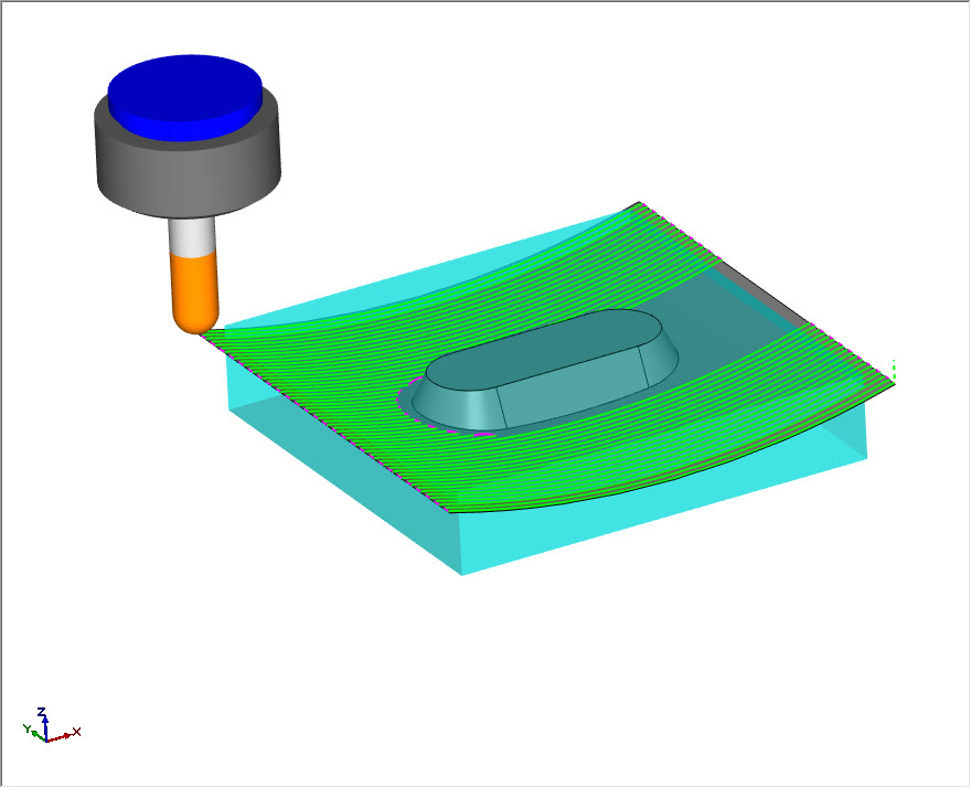
6) When using wireframe as a boundary, how much should you offset for the tool?
The tool center will be driven to the boundary by default with 3D toolpaths. In most cases, this is best. But there are cases where you might want the tool to stay inside or go outside the boundary. This is why the boundary options give you the options: center of tool, tool inside and tool outside. When using inside or outside, the boundary is adjusted by half the tool to either the inside or outside.
7) How can you force the tool to start cutting outside of the stock?
This depends on which 3D toolpath you are using. For example, the advanced roughing toolpath uses the stock geometry as a 3D boundary. So this particular toolpath will start off the stock by default, unless restricted by a boundary.
As far as your semi-finish and finishing operations, those are geometry driven. So if you want the tool to start off the part, besides using a lead in, you would extend the geometry that you are driving the toolpath along. This is true for Mill Standard and Pro toolpaths. When using the surface based toolpaths, extensions are built in – eliminating the need to edit geometry directly.
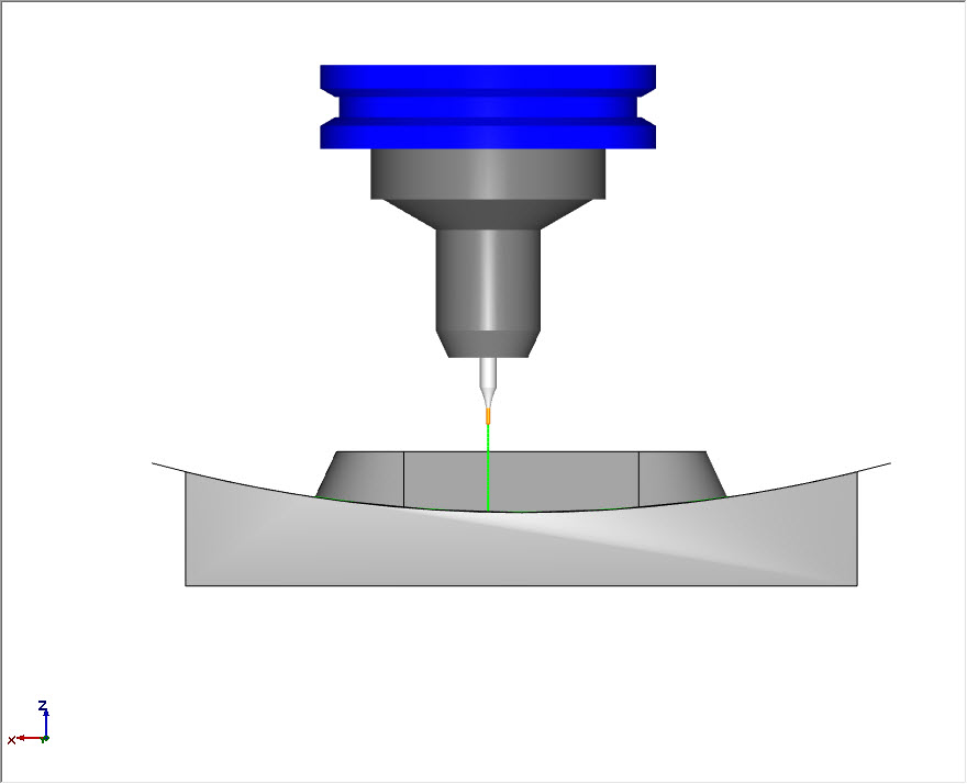
8) How do you cut sharp corners on 3D parts?
In many cases, there is a smaller radius at the intersection of floors and walls – which we would clean up with either a pencil toolpath or a project curves toolpath. If it’s a sharp inside detail, then we would use EDM to burn that detail in.
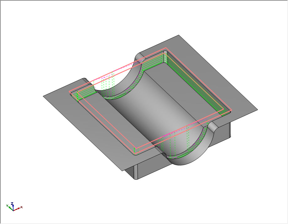
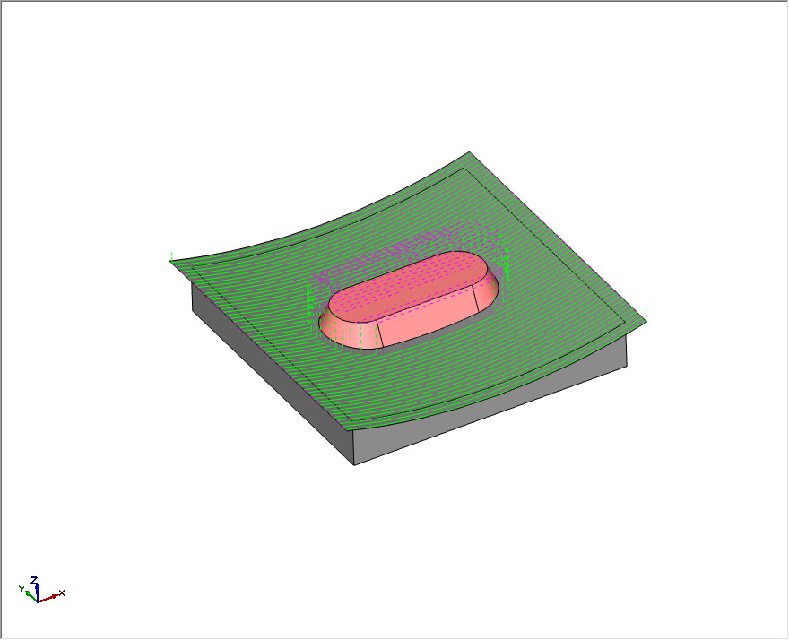
9) What options do you have for trim and re-link when using check surfaces?
There are 6 options for trim and re-link. Depending on the check surfaces you’ve selected, you’ll find these tools handy. Let’s take a look at 3 of these.
Trim Collision Only
This option only trims out toolpath that contacts with the check surfaces.
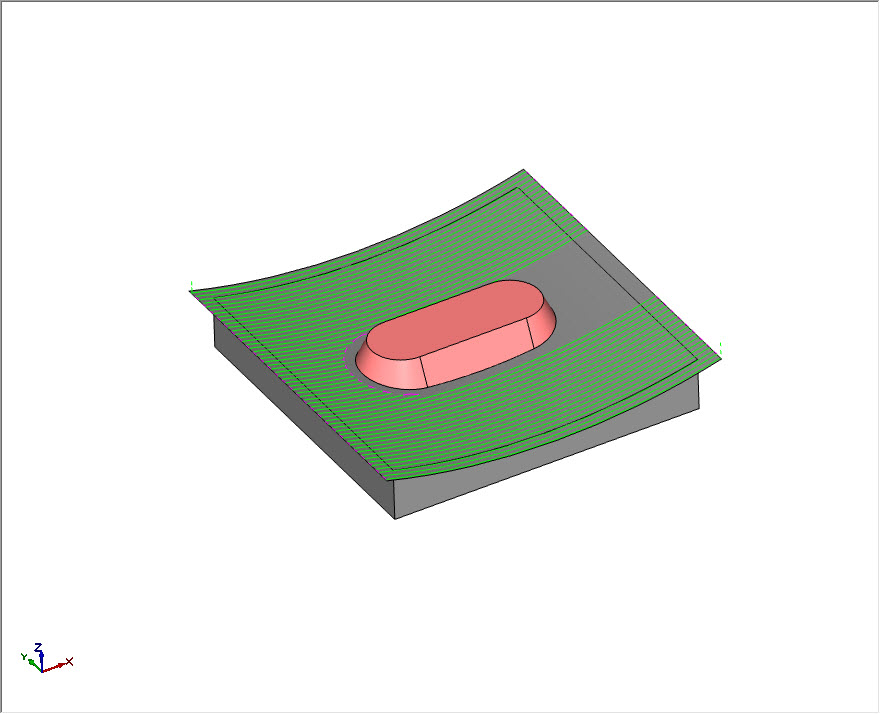
Trim After First Collision
This option will trim away the toolpath after the first contact with a check surface. In this example, you can see on the right side of the check surface that no toolpath was created. Unlike the trim collision only option, we are keeping the tool down and on the part.
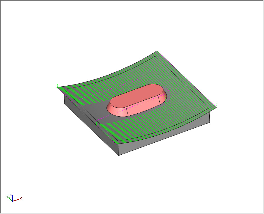
Trim Before Last Collision
This option is the invert of the trim after first collision option.
10) When using the retract option with check surfaces, are your rapid positions affected?
No – the retract values set at the feature level are used for the rapid reposition even when using check surfaces. If the retract value “breaks through” this plane, the software will warn you so you can update the rapid plane / clearance plane value to accommodate the retract settings you’ve defined.
11) How can I let the tool travel outside of the boundaries if I need it to?
Using the boundary option of tool outside, the tool will be driven outside the boundary by half the tool. If you need to extend it further, there is a user input to add an offset amount.
12) Does advanced rough work with check surfaces?
Yes – all of the Mill Pro toolpaths have the option for check surfaces.
13) Can you use a negative allowance with check surfaces?
No – the allowance value must is a positive number.
14) What types of tools would you use for 3D surface machining?
It really depends on the type of work you are doing, but you’ll find end mills, ball end mills and bull nose to be the most common for roughing, semi-finishing and finishing.


I found the Q&A useful. It provided more info on some features and reinforced some of the techniques shown.
Thanks David! If there’s ever any topics you want us to cover or have questions on – just let us know.
In #7 you mention “…surface based toolpaths…”. Can you explain what you mean by this?
https://bobcad.com/5-great-reasons-to-use-cam-software-surface-based-toolpaths-for-cnc-machining/
Good stuff guys, thank you! Really appreciate all the help you guys have provided for this excellent program.