CAM software is becoming increasingly more vital to the machining industry. As various machine shops look for a competitive advantage, they need look no further than the dynamic capabilities of CAM software. When coupled with CAD software, CAM and CAD have the ability to streamline the machining process immensely. CAM and CAD usually go together unless the product is a CAM plug-in compatible with SOLIDWORKS™, AutoCAD or something similar. Let’s delve deeper into what makes up CAM software.
CAM Overview
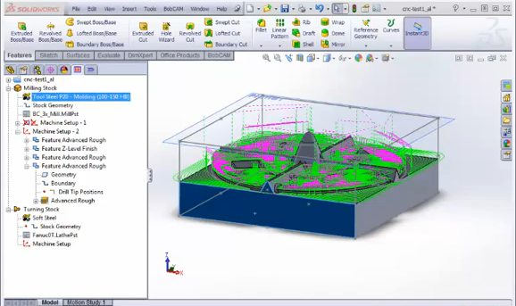
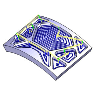
Computer-Aided Manufacturing software provides manufacturers with indispensable benefits. It allows users to set up their job within a Job Tree, choose the Toolpath and run a simulation of what their part(s) will look like when finished. Simulation can save machines and programmers a lot of trouble by detecting any errors before they would’ve happened. That includes detecting possible crashes, tool collisions or miscut parts resulting in wasted material. After you have designed your model in the CAD part of the software, it’s time to begin the process that ends with your design in-hand. Programmers will begin by structuring their Job Tree, setting the Toolpath and defining the tools they want to be used. When they are happy with the aforementioned, they typically run a simulation to make sure the machine understands exactly what they have asked it to do. Once satisfied, users can now generate the g-code for their CNC machine to follow when cutting the part. Generally, CAM starts with a Roughing cycle to remove the bulk of the material. As it nears completion, semi-finishing and finish Toolpaths are applied and your part is ready for use.
Subscribe to BobCAD-CAM's CNC Software Blog
Join your fellow manufacturers! Get BobCAD-CAM’s latest CAD-CAM articles straight to your inbox. Enter your email below:What’s A CAM Plug-In?
BobCAD-CAM makes a product called BobCAM for SOLIDWORKS™. These are 2 separate products that work hand-in-hand as a plug-in. This CNC machine technology can easily be integrated inside your SOLIDWORKS, allowing you to easily create 2, 3, 4 & 5 Axis Toolpath and generate g-code for your CNC machine. In an effort to remove the guesswork from machining, BobCAM CNC CAM software provides the programmer special machining wizards for all milling strategies. Modules that address 4 & 5 Axis machining features, Dynamic Machining Strategies™, High-Speed Adaptive Roughing Toolpath strategy and Full Machine Simulation. Simulation allows you to use your specific machine’s kinematics for the most accurate Multiaxis posting and simulation support. The latest BobCAM offers both standard 2 Axis machining capabilities and multi-tool drilling, as well as add-ons for 3, 4 & full 5 Axis simultaneous CNC Milling.
Default Functions in Your CAM Tree
While setting up a job in your CAM software, you will be using a CAM Tree (Job Tree) to help keep the job organized, establish Toolpath and eventually generate g-code. Let’s break down the listed default settings. Displayed at the top of your CAM Tree is a folder labeled “CAM Default Folder” and contains commands to many of the default CAM settings as well as job creation. Use the right-click shortcut menu to easily access the aforementioned commands. Stored in the CAM Defaults folder are the following functions:
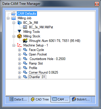
- New Job- This will open your Machining Job dialog box, allowing you to select a job type and CNC machine type.
- Current Settings- Accesses your Cutting Conditions Default dialog box so you may define various machine and posting defaults, as well as machine creation.
- Cutting Conditions- This opens your Cutting Conditions Default dialog box, allowing you to define cutting conditions for your hole drilling and tapping operations.
- Tool Pattern- Your Tool Pattern dialog box lets you modify operation templates used for all feature types.
- Tool Library- Use your Tool Library to create/modify the tool database.
- Mill Tool Holders- The Milling Tool Holder Library is there for you to create/modify the Milling tool holders and arbors.
- Adapter Library- Utilize the Adapter Library to define all tool holding adapters for Mill Turn machines.
- Thread Library- The Thread Library dialog box lets you define the parameters for all tap thread types.
- Material Library- Opening your Stock Material Library will allow you to define the speeds and feeds used for all materials.
Editing Your Toolpath in CAM
This function is exclusively found in BobCAD-CAM V30. Once you have your desired Toolpath selected and laid out, BobCAD-CAM gives users the ability to modify that path as they see fit. Be aware that there is no guarantee that an applied modification will be gouge-free or create unwanted motion. Use caution and simulate prior to cutting your part to establish possible errors. Using Command Mode, users can choose the type of action performed on the selected Toolpath elements. The actions available in Command Mode are as follows:
- Delete- Gives users the ability to delete Toolpath entities and relink the Toolpath.
- Trim and Relink- Create a trimming boundary to trim portions of Toolpath away.
- Move- Use Move to alter the location of your selected Toolpath.
- Replace- Lets you draw in your own custom Toolpath and replace entities of the Toolpath with this CAD geometry.
- Break- Split your Toolpath entities into different segments.
- Modify Attributes- Use function to edit the Feedrate or feed type.
- Extend Cut Move- Extend the Toolpath slightly by a specified distance.
- Edit Tool Axis- Here you get the option to edit the tool orientation for the selected Toolpath elements.
How To Set/ Edit Post Processors
BobCAD’s Job-Based CAM Tree supports the setting up and programming of different machines and machine configurations. Users choose a machine configuration and a post processor to format the g-code for their NC files.
Users can associate machine configurations and post processors so that when choosing a machine, they also choose the correct post processor. They also can default a machine/ post.
A Post processor is a text file located in the BobCAD post folder C:\BobCAD-CAM Data\BobCAD-CAM V30\Posts\Mill. This text file is used to format the g-code posted by the CAD-CAM software. Because the post processor is a text file, anyone can make changes to it, making it easy to customize g-code formats.
If you are new to making edits to BobCAD posts then you’ll be happy to know all the post variables and API calls are documented and come with the software. C:\BobCAD-CAM Data\BobCAD-CAM V30\Posts\Documentation.
Download a trial of BobCAD-CAM V30 today for the latest CAM technology!
You’re one click away from subscribing to BobCAD’s YouTube channel. Click the link below for tips, how-tos and much more!


Leave a Reply