Tech Tuesday is a weekly blog that addresses some of the most common questions and concerns that I hear throughout the previous week from users of BobCAD’s CNC software. Both customers and future customers are more than welcome to leave a comment on what they would like to see covered for the following Tech Tuesday.
This Tech Tuesday will highlight some Multiaxis milling operations that are offered in Mill 4X Pro and Mill 5X Pro of BobCAD-CAM. This part file, as an example, has 4 pockets that follow the curve on the top of the part. We will be looking at three different operations: Morph Between Two Curves to face off the curved top of the part, Multiaxis Machining operation to rought out the pockets, and Swarf Machining to finish the sides and bottom fillets of each pocket.
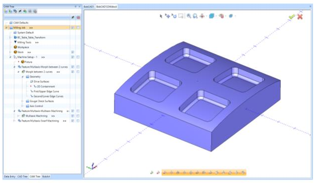
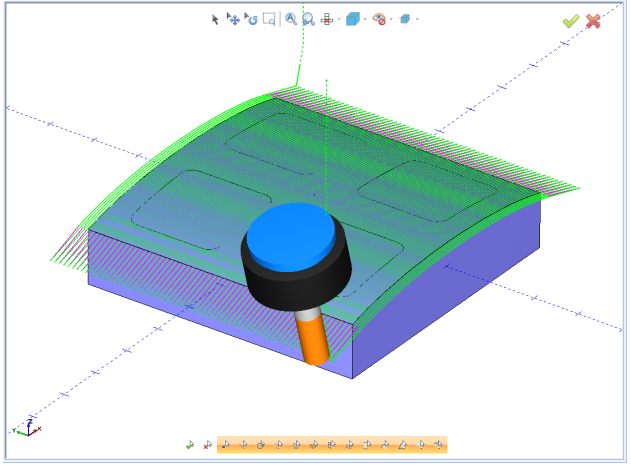
The first operation we will look at is Morph Between Two Curves. First, there was some CAD work involved, where we went to Create 3D>Untrim Surface to create the curved surface we will be machining down to in this operation. Then we created the Milling Job with a rectangular stock that has a height just above the example part file. We also defined the machine as 5-axis with the rotary axes in A and B rotation. After defining the Machine Setup, we right-clicked on Machine Setup – 1 and selected Mill Multiaxis. Under the surface-based toolpaths, we selected Morph Between Two Curves and used the default half-inch flat endmill. We selected that top surface as the drive surface, then selected the front edge of the surface as the first edge curve. We selected the back edge, or the one furthest away in the Y direction, as the second edge curve. We set the Tool Axis control as 4-axis with the rotary axis as Y. Lastly, we set the lead-in and lead-out settings accordingly for this operation.
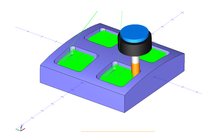
The next operation we will be focusing on is a Multiaxis Machining operation. This is normally used as a roughing operation in either 4 or 5-axis milling. Like in the previous operation, we begin by right-clicking on Machine Setup – 1 and selecting Mill Multiaxis. The Multiaxis Machining operation is the second one down in the operations list. After selecting the Multiaxis Machining operation, we defined the tool as the same one used in the previous operation.
We set the parameters on the next page pertaining to our preferences. We kept the default stepover and depth step for this operation. The only setting changed on this page was the cutting method from one way to spiral to save time in the machining process. The next tab is the Part Definition tab where we define the geometry used for the operation. For Part Surfaces, we selected all of the side walls and fillets around the side walls of the four pockets. For Floor Surfaces, we selected the floor surface of each of the four pockets.
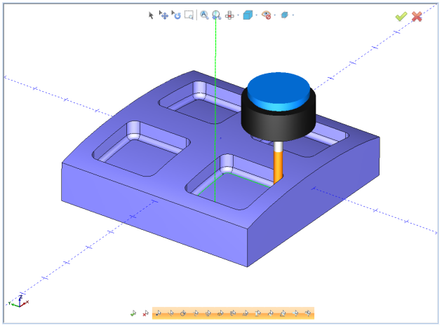
The final operation in this Tech Tuesday is a Swarf Machining operation. This operation is in the Mill Multiaxis Wizard just as the previous two operations. After selecting Swarf Machining in the operations list, we then defined the tool as a quarter-inch ball endmill for this operation to finish the side walls and the fillets around each pocket. Under the parameters of this operation, we selected the swarf surfaces as all of the side walls of each pocket. This operation is automatically set to a 5-axis milling operation. You can set other options like linking and lead-in/lead-out for the operation to your desire. After clicking compute, you can now simulate the operations and generate the G-code for your specific milling machine.
This information is also found in our Knowledgebase for common questions about various functions in BobCAD-CAM. Our Knowledgebase documentation can be found here:
www.bobcadsupport.com
Our user forum is a community of other BobCAD-CAM users to share ideas and projects in BobCAD-CAM:
forum.bobcad.com
Download a free demo version of BobCAD-CAM today!
BobCAD-CAM has provided CAD-CAM CNC Software products to the global manufacturing industry for over 30 years. BobCAD-CAM software can be found to increase CNC productivity for many applications in aerospace, automotive, production manufacturing, mold making, general machining, woodworking as well as the medical manufacturing industry, consumer products, musical instruments, custom fabrication, defense industry and many others due to the products ability to automatically generate NC programming code for such a wide variety of CNC controllers. BobCAD-CAM software is also found in educational institutions throughout the world as well as independent hobby home use. Products include machining technology for 2, 3, 4 & 5 Axis CNC Milling, Routing, Waterjet, Plasma and Laser machines as well as 2 Axis CNC Lathe. BobCAD-CAM is modular allowing shops to start off at a reduced technology level and add technology as it is needed including an add-on, BobART, for artistic machining. Unique technology includes adaptive high-speed machining multiaxis milling and routing which is a first in the world of CAD-CAM software. BobCAD-CAM also provides a variety of quality training products that include regional and online training classes or private sessions tailored to specific applications. Professional certification and multi-tiered support solutions are available. Contact BobCAD-CAM directly for more information at 877-262-2231 or 727-442-3554
New Feature Spotlight – Tell us the topics that are most important to you Click Here


Leave a Reply