 Clearwater, FL – Much has been published in recent times about High Speed Machining and how it relates to CAD-CAM Software. Including the technology and the long list of HSM benefits. As a cad-cam software provider we wanted to contribute to the subject in the name of education and to include that BobCAD-CAM software does offer HSM capabilities in toolpath machining strategies for CNC Milling and routing.
Traditional Offset versus High Speed Toolpaths
The term, “Toolpath” is used to visually display and describe the route in which the CAM side of the software tells the cutting tool to machine the geometric regions of the part model. It’s the path that the tool takes when machining. Toolpath is going to be basically being defined by the part or areas that the user has chosen to machine, the size of the tool being used, the cutting regions for those tools and the type of machining strategy that is used. That is toolpath whether it’s for a mill, router, laser, burning machine, waterjet or cnc lathe. There is a lot of other data that is included in the creation of a NC Program that has to do with post processing parameters such as speeds and feed rates based on strategy, material and tool data and more. Machine controllers can be different in how they want to see the g-code for the program to be read properly by the controller. That is toolpath.
More than one toolpath is typically used to perform machining operations. Generally this will be a “Roughing” and a “Finishing” operation. Roughing is generally the first stage of machining.
This is where multiple step downs by the tool, remove the bulk of the material.
The second operation will be the finishing operation to complete the machining phase. There is also “Semi-Finishing”. An example of this would be the use of a Z-Level Roughing operation to remove the bulk of the material. Then a Z-Level Finishing operation to “semi-finish” the part and lastly a “Equi-Distant Offset contour” operation to finish the part off.
By employing the use of High Speed toolpaths into your machining operations you can achieve excellent results faster than by using traditional offset toolpaths. Even in the world of 3D machining.
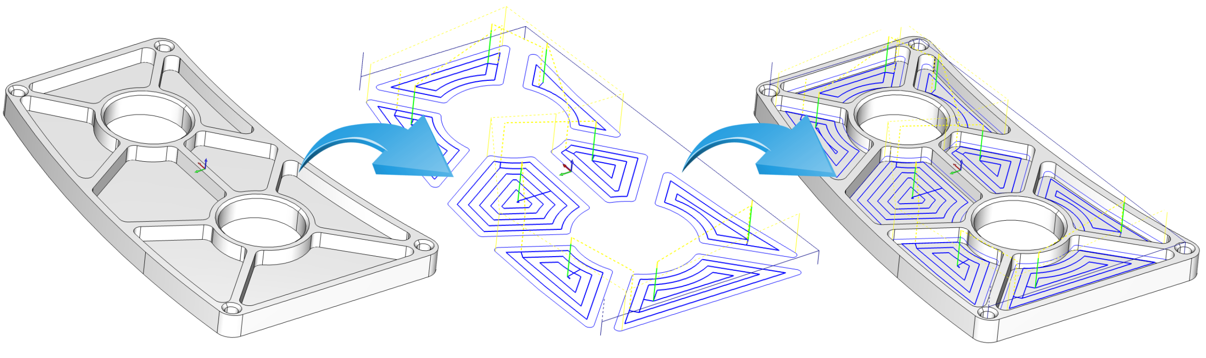
BobCAD-CAM software offers a unique Advanced Roughing operation that includes the option to use an Adaptive High Speed machining technique. This was specifically added to give the programmer an advantage in roughing out 2D or 3D regions of a part, or the entire part.
 Boundaries can be created and used to segregate the toolpaths into specific regions of the part, deep cavities or regions that require a smaller tool to machine. This would not be used to replace a REST operation. An advanced REST machining operation would be used as a part of the finishing process to clean up areas where the larger tools were unable to machine.
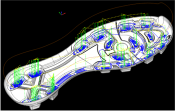
BobCAD-CAM software is used to produce the toolpaths for all of the images in this article. Traditional offset toolpath has been the most common form of toolpath in use since the advent of CAM software. However, as more and more shops begin to use HSM they are trusting it more, becoming less critical and beginning to enjoy the benefits of it. The goal of using a trochoidal form of machine path is to limit the number of collisions that the cutting edge of the tool has with the material, reducing chip load, better utilize the cutting tool itself by using more of it while taking deeper cut depths and all while at much higher speeds.
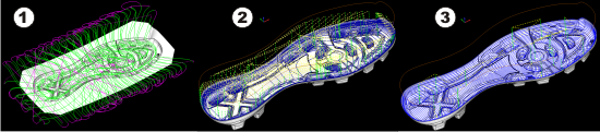
There are distinct differences in toolpath operations, planar (1), offset (2)and high speed (3). Here you can see each of them in a simple 2D example.
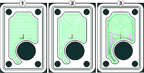
Planar (1) is the most fundamental of the three and is basically a back and forth slice across the material. Options for this style of toolpath would include the ability to machine in one direction (zig) and back and forth (zig-zag). You should also be able to determine a cut direction (climb or conventional), determine a “Lace Angle” parameter and a step over for the cutter. Some CAM systems will allow you to include a side allowance and a bottom allowance so that material can be left over for a finish pass. Tool lead-ins and lead-outs will often times be limited to a plunge, ramp or a spiral lead-in when using this type of strategy, each option definable through input parameters. In addition, compensation controls can be available for the finish pass. These options would include the availability of a complete tool database/library with tool crib and tool holder libraries as well as a complete material database/library. CAM software is designed to organize these strategies and associated variables. BobCAD-CAM has developed each machining operation into “wizards” that step the operator through the procedure so that the features are organized and no variable is left behind. This makes the process easy to understand and get through.
In addition, the CAM software allows for the overwriting of system tool parameters so that the experienced operator is not limited. These would include the use, or not, of system tools, tool height and offset values, speeds and feed parameters for the operation. These operations should also allow for the slowing down of the tool when entering an arc corner (when not using HSM).
Offset (2) is most common in cnc machining open or closed wall pockets and slots in a 2D/2.5 Axis (X, Y and Z step down) program. Very similar to planar, this type of operation in a CAM system is going to have the same variable inputs. The difference is whether you want to create an offset IN or an offset OUT. These concentric offsets will either start outside working their way toward the center of the specified cutting area or start in the center and work their way toward the outer wall or defined area. All of these operations in a CAM program will also include single step or multiple step options. This is where a total depth is either automatically calculated based off of the part model or manually input by the programmer. A depth of cut is entered and the CAM program should automatically calculate the number of Z-Cuts needed to machine (rough) the part region.
The offset toolpath will typically have many right or left turns where there can be a lot of stop and go occurring with the tool while machining. The more times this happens the more wear and tear there will be on the tool. Often times this type of toolpath will produce higher levels of vibration as well and require spending more money on tooling for jobs that have cutter designs that minimize heat in the cutting zone in order to reduce power consumption as well. Offset toolpath can lead to higher rates of tool deflection which can also lead to parts being cut out of tolerance and poor surface finish results. This means that higher speeds and feeds often times cannot be used. While offset toolpath can be very useful, it is the High Speed toolpath strategies that provide the greatest benefit.
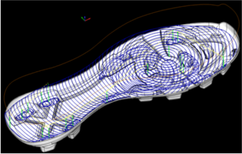
High Speed (3) machine toolpath (HSM) strategies, also known as “Trochoidal” machine toolpaths open the door to a number of important benefits.
 Most shops are cutting faster today than they did ten years ago. Albert Einstein said it first and best, “All motion is relative.” From that perspective, incremental improvements in “rate” mean that a shop is machining at high speeds relative to what it did previously. Increasing the feed rate of a ball-nose end mill in tool steel from 12 to 24 ipm and spindle speed from 4,000 to 8,000 rpm is a 100 percent increase in cutting speed and well within the capability generally found on most CNC machining centers.
In addition, as the cutter creates a chip, the heat generated by that action is transferred to the chip. When the chip breaks and leaves the cutting zone, the heat is carried away with it. A big advantage of high speed machining is that at elevated rates of speed and feed, the chip is cut and evacuated so fast it tends to transfer little or no heat to the green workpiece. In many cases this eliminates the need for coolant. At conventional machining speeds, there is time for heat to move from chip to uncut metal and create a work-hardening condition. This increases the force needed to create a chip, which creates more heat, and so forth. Coolant mitigates the cycle by reducing the temperature in the cut zone and flushing away the chips. However, at very high rpms, the tool rotation throws coolant away from the cut zone so without very high pressure or through-the-tool piping, it never reaches the cutting zone. Trapped chips can remain in the cut, allowing them to be re-cut by the tool. Therefore, an air blast is very efficient for evacuating chips in high speed applications.
High speed machining can certainly help a shop manufacture more accurate parts with better surface finishes. And often, because a machine tool and workpiece setup has to be very rigid for high speed machining, the results are more consistent workpieces. All of this together amounting to higher efficiency in CNC programs, machining and in the end, increased profitability for a CNC business.
 SOME HISTORY…
Years ago, in the beginning of NC, each block of data was executed in order, one at a time. Speeds were sufficiently slow that this was a workable arrangement, especially for drilling and 2D linear milling operations. It was when the machine needed to execute a curve or contour that the need arose for seeing what kind of data was ahead in the program. Otherwise machine momentum would cause the cutter to overshoot or undershoot a programmed change in cutter direction, wreaking havoc on the workpiece. That need lead to the development of look-ahead, which is requisite for high speed machining of any geometry except for linear, single-axis moves. If your CNC controller doesn’t have a look-ahead feature, it needs to be upgraded for high speed machining. In 2013 there are many affordable solutions to this such as Mach3 by Artsoft that can help ramp up those older machines.
Taking The High Speed Route To CNC Profitability
We really do not see a training book that specifically addresses high speed machining and CAD/CAM together. However, CAD/CAM software is an absolute necessity for the creation of these types of machining toolpaths. Without CAD-CAM software they wouldn’t exist today. The benefits listed in this paper outline all of the reasons why shops should take advantage of this technology. And now, high speed adaptive roughing strategies being available through BobCAD-CAM for Multiaxis cnc machining for the first time, opens the door for even more complex cnc work to take advantage of its powerful abilities and profit-building results. Machine time is money and the reduction in cycle times that lead to faster turn-around, happier customers, better finish results, reduced tooling expenses and a longer life for your cnc machine tool all equal profit and better business practices.
For more information high speed CAD/CAM machining technology, you can contact BobCAD-CAM directly at 877-262-2231 or 727-442-3554.
Download a Free BobCAD-CAM Software demo HERE


Basically, it is all about the software used. The more advanced and updated the software, the better the results. Errors are common in Computer Aided technology but it will be prevented with constant software updates.
CNC milling CNC lathe operator