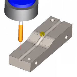
BobCAD-CAM’s newest CAD-CAM module, Mill 3 Axis Premium, is giving users the tools they need to be successful and profitable. In this example, we will highlight how effective the Project Curves Toolpath is in Mill 3 Axis Premium. To illustrate this, we will machine a radius slot on a 3D curve using a ball mill.
First, let’s take a look at the steps it will take to set this job up, the Toolpaths you will be using and the options within that Toolpath you will have to get this done. As we begin our project, the part comes in as a SOLIDWORKS SLD PRT file. Personally, I like to start my workflow from a top view of my part. This is to replicate how the spindle on your machine will be looking down, but feel free to start however you feel most comfortable.

Now, let’s set up our geometry. Utilizing the Mill Premium Projection Toolpath means we need to have geometry to project. The first thing we will want do is create a new layer and make it active. Next, open the Utilities menu and select Extract Edges Single to start your Wireframe geometry.
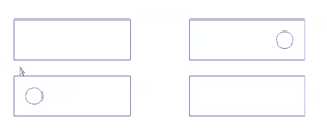
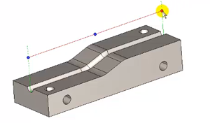
As we begin inputting our geometry, you will want to join a line between the boxes, utilizing the Line Join function to run another line down the middle, creating a centerline path.
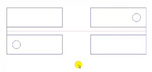
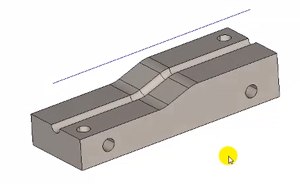
With our centerline now established, the next move is to translate the geometry up. This can be accomplished by selecting the Utilities menu and then hitting Translate. Pull your geometry up in Z with your mouse, hitting OK when complete. Your model now has a line to follow that represents your Projection Curves.
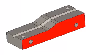
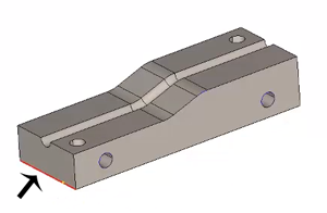
Since we will want to simulate the model later to see what is going on, we create a new layer called stock. To address our stock profile, go into the Utilities menu, Extract Edges and Single. Click on the red highlighted face (pictured below), click the spacebar, right click, then select Cancel.
So, now let’s figure out the length of the front of my part since we will need to extrude. Click Measure, select the edge you want and then you can see the measurement is an inch and a half.
From here, go to Surface, Extrude Curve and input your geometry. This represents the stock. We now have the solid for the stock, the part model and the Projection Curves Toolpath selected. At this point, CAD steps are pretty much done and it’s time to run this through the stock wizard. Use the model we just created as our stock.
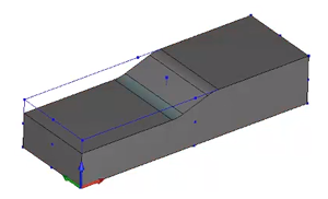
For our zero position, select the top corner of the part. Go in and choose Edit, adjusting your layers accordingly. Now, the zero is set up, the stock is set and Projection Curves is selected; we are ready to go. As we blank out the stock, select Blank in the Data CAM Tree Manager.
Following that, right click on Machine Setup, select Mill Multiaxis and then select Project Curves. Selecting Next will take you to the tool setup.
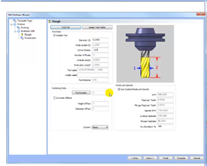
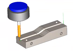
While we are in the tool setup, you will want to select Projection From Edit Curves, then edit the drive surface. We want the drive surface to be like the 3d radius groove below, selecting it with the space bar.
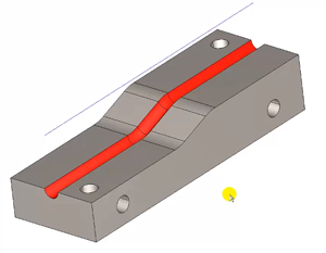
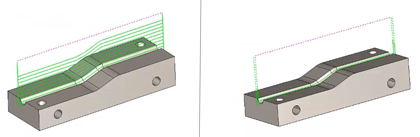
Next, compute your Toolpath. To see what’s happening, you can utilize Backplot for a visual like below.
Using Backplot, we are looking at where the tool starts on our model and what direction it goes in. We don’t want to take this in a single pass, we will want to take multiple passes. Now, do we want it to cut uphill or downhill? Let’s address the direction of the cut. Right now, simulation has the tool going left to right. To change direction from right to left (downhill), we go into Parameters in our Wizard, go to the Start Point option, set point by position, Pick Point or Pick A Line, From here you will select Pick, turn the projection geometry on, hit shift, left click for snap points, selecting the dotted line on the right, hit OK and then recompute. Now our tool is moving from right to left (downhill).
Since we don’t want the tool to plunge directly into the part, we will edit the Toolpath to start away. We could use the Lead-in option, but I am going to use an extension in Extend/Trim. This extends the tool to start off and away from the material, slowly working its way in.
We are now at a finish pass and need to rough this out, using multiple steps to get down to the bottom. In your Parameters tab, choose Depth Cuts, input the numbers of passes you want and the spacing, hit OK and then compute.
If you notice any air cutting, simply turn your roughing on, check the box that says ‘Stock Def. Parameters’ on and then hit compute. That will trim out the Toolpath that doesn’t penetrate the material.
The way I have my tool going is in a single direction and then rapiding back, but depending on the material or Toolpath you are using, you may want the tool to go in a back and forth motion. To change those options, go back to Parameters, click Sorting Options, ‘connect splices by shortest distance’ and finish the task by hitting OK. This gives you that back and forth Zig Zag pattern instead of going to clearance all the time. So, there you have it. That is how you use Mill 3 Axis Premium Toolpaths to machine a radius slot that is on a 3D curve!

You’re one click away from subscribing to BobCAD’s YouTube channel. Click the link below for tips, how-tos and much more!
Posted March 9, 2018 12:45 pm
Summary
Article Name
CAM Software Tutorial: Machine A Radius Slot On A 3D Curve
Description
BobCAD-CAM’s newest CAD-CAM module, Mill 3 Axis Premium, is giving users the tools they need to be successful and profitable. In this example, we will highlight how effective the Project Curves Toolpath is in Mill 3 Axis Premium. To illustrate this, we will machine a radius slot on a 3D curve using a ball mill.
Author
Michael A. Downss
BobCAD-CAM Software


Leave a Reply