


Emboss Regular Example 1
Introduction
This help topic provides a basic example to help you get started creating Emboss Regular features. By providing the fundamental information about this feature type, this topic can be useful for beginners or advanced users alike.
For this example, you start from a new file. The entire process of creating an Emboss feature is explained.
Important Notes
-
There are two geometry items used: the feature geometry and the cross section.
- The feature geometry defines the boundary of the feature (in X and Y).
- The cross section defines the shape of the emboss (in Z) at the edge of the feature geometry.
- The feature geometry must be a closed loop.
- One or more closed loops can be selected for a single feature.
Overlapping areas of multiple chains are not included in the
Part 1) Create Geometry
The Emboss Regular feature requires that the geometry used for the feature is a closed loop. The geometry can be any combination of lines, arcs, and splines, but the entities must share the same start and end point (closed loop).
-
In the File menu, click New.
- With the Part option selected, click OK.
The new part opens with the Feature Manager Design Tree open. - Ensure the document is set to inches.
- Click Front Plane, and select Sketch.
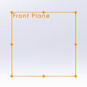
The Sketch ribbon becomes available. -
Select the Center Rectangle function.
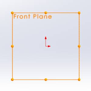
The function opens in the Property Manager - Move your mouse to the origin.
-
With the point visible, click the origin.
- Move your mouse up until a value of x = 4 , y = 4 is reached, and click again.


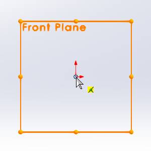
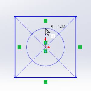
- Select the Circle function.
The function opens in the Property Manager. - Move your mouse to the origin.
- Click the origin.
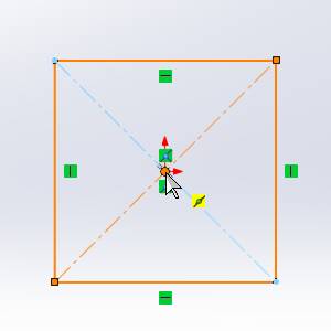
- Move your mouse up until a value of 1.25 is reached, and click again.
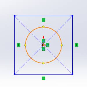
- Click Exit Sketch.

Part 2) Create the Canvas
-
In the
 BobART Manager right-click
 Emboss Model,
and click Create/Modify Canvas.
Emboss Model,
and click Create/Modify Canvas. -
By default the UCS is set to
-
In the Origin group of the Canvas Definition dialog, double-click in the X field so that the entire value is selected.
Enter -
In the Y field, enter
The Origin settings define the lower-left corner (origin) of the canvas in the graphics area. The Origin values set the distance from the WCS or world coordinate system. This is also known as
the CAD coordinate system.
WCS or world coordinate system. This is also known as
the CAD coordinate system. -
For this example, in the Canvas Size group, the default values of X=5 Y=5. are used.
These values represent the length of the canvas along each of the X- and Y-axes. -
To set the color of the canvas, click the drop down for Canvas Color. In the drop down, click a color, or choose More Colors.... For this example, click
-
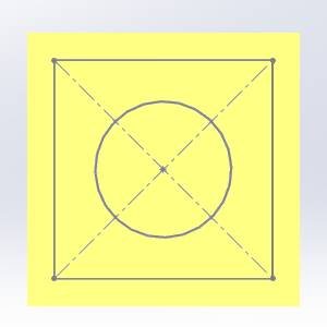
The canvas definitions are now defined. To create the canvas, click OK.
-
Click Cancel to close the dialog.
Note: Notice the location of the canvas origin (lower-left corner). Also note
that the geometry created earlier is contained within the bounds of
the canvas.
The canvas for embossed models is created with zero
thickness.
Part 3) Add the Feature and set Attributes
-
In the
BobART
Manager, right-click Emboss
Model, and click Emboss Regular. -
In the Emboss Attributes group, click at the start of the text in the Name field and type My so that the description displays My Regular Emboss 1..
-
To define the color of the feature, click the drop down next to Color and select the desired color.
You can also access additional colors by selecting More Colors.... You can then select the desired color and click OK. -
In the Application Type group, ensure Add is selected.
Part 4) Select Geometry
-
By default the Selected Geometry list has focus.
In the graphics area, select the arc you created earlier.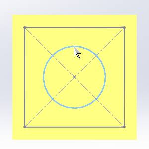
The arc is added to the list.
Tip: When selecting
geometry for Emboss features, you often need to hide the embossed model.
To hide the Embossed model/canvas:
• Right-click Emboss
Model, and click Blank/Unblank.
• Click the ![]() (Blank/Unblank) button in the quick access menu of the BobArt Manager.
(Blank/Unblank) button in the quick access menu of the BobArt Manager.
Part 5) Cross-Section
-
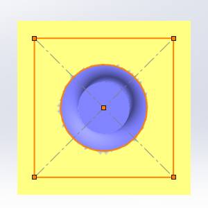
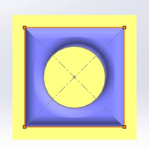
By default the Cross-Section is set to Convex Arc.
In the Radius field, type 0.500. Notice that the cross section preview is updated in the dialog.
All of the other settings remain at the default values. -
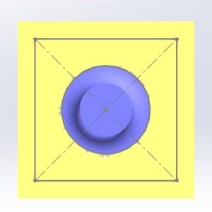
Click OK.


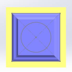
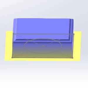
Notice that the feature geometry defines the boundary of the emboss, and the cross section defines the shape of the emboss vertically in Z. The Application Type, Add, means that the feature is added (or raised) in the positive Z-axis. The Z-height of the feature is -
Click Cancel to exit the feature.
Part 6) Editing the Feature
After creating an Emboss Regular feature and exiting the dialog, you can edit the feature to make changes to the model. To edit the feature, you use the Emboss Feature in the BobART Tree.
-
In the BobART tree, right-click
 My
Regular Emboss 1 - Add, and click Edit.
My
Regular Emboss 1 - Add, and click Edit. -
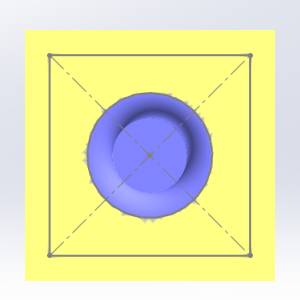
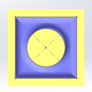
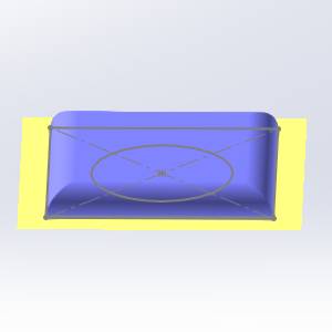
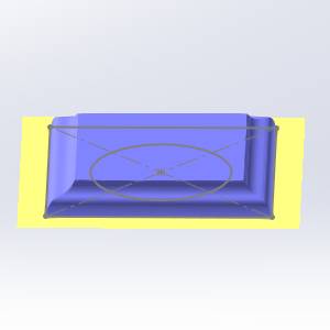
In the Emboss dialog, click the Cross Section arrow and click Concave Arc.
-
Click OK to regenerate.

Again, you can see that the emboss starts at the boundary defined by the feature geometry, and the cross section defines the shape of the emboss in Z. -
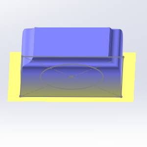
In the Emboss group, click the Application Type arrow and click Subtract. This means that the feature is lowered in the negative Z-axis direction.
-
Click OK.
-
Click Cancel.
Part 7) Select Multiple Chains for a Single Feature
The following section shows how the Emboss Regular feature handles more than one geometry selection.
Tip: In
the BobART tree, click ![]() My
Regular Emboss 1 - Subtract. Notice that the feature geometry is
highlighted in the graphics area. You can use this preview to locate each
feature when the BobART tree contains multiple features.
My
Regular Emboss 1 - Subtract. Notice that the feature geometry is
highlighted in the graphics area. You can use this preview to locate each
feature when the BobART tree contains multiple features.
-
In the
BobART
tab, right-click  Geometry, and click Re/Select.
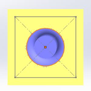
Notice that the previous feature geometry is still highlighted. This shows that it is still selected. -
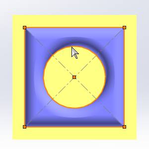
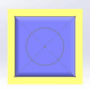
Select the rectangle.
-
Set the Application Type to Add.
-
Set the Cross Section to Convex Arc.
-
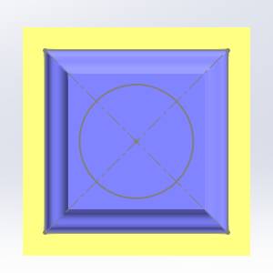
To update the model, Click OK.
Notice that the common areas of the two loops are not included in the emboss.
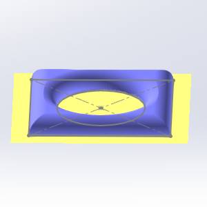
Part 8) Change the Feature Geometry
-
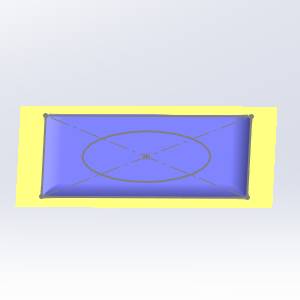
Remove the arc from the Selected Geometry list by highlighting it and deleting it from the list, or my deselecting it from the graphics area.
-
To update the model, click OK.

Note: Notice that the result is the same as that created in Part 5. The only difference being the feature geometry is now a rectangle. The Z-height of the model is because of the defined cross section.
Tip: When using the cross-section types, Convex Arc or Concave Arc, you can modify the start and end of the cross section to change the result. This is shown in the next part of this example.
Part 9) Modifying the Cross Section
When using the cross-section types, Convex Arc or Concave Arc, you can modify the cross section using the Start Angle and End Angle parameters.
-
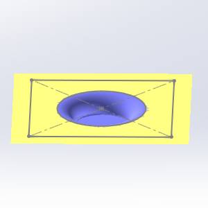
In the Emboss dialog, in the Start Angle field, type 45.00.
This causes the cross section to start at the midpoint of the arc (45 is half of 90). The range of possible values for the Start Angle and End Angle are from 0.00 to 90.00 degrees. -
To close the dialog, click OK.
-
To view the change in the model, Regenerate.
Note: The Z-height of the model is now much lower than
the previous result. This is
Part 10) Modify the Cross Section in the Emboss Dialog
When using any of the standard cross-section types in the Emboss dialog, you can manually edit the cross section using the cross section preview that displays in the dialog.
-
Click the Cross Section drop down and select Spline.
-
In the preview, click the red point on the right side. Drag (click and hold the mouse button) the point up to the


-
Click and drag the first point (on the left) up to the


-
Click and drag the second point down to about


-
Notice that the parameters of the three points are updated in the Cross Section group.
-
Click OK.
Part 11) Using Fast Edit
The Fast Edit section of the Emboss dialog is used to scale the cross section or to add a base height which creates a wall at the bottom of the feature.
-
In the Fast Edit group, set the Base Height to 1.00.
-
Click OK.
Notice the height of the model has been lifted by adjusting the base height. -
In the Fast Edit group, set the X-Y Scale to 0.500, and set the Z Scale to 0.500. These settings cause the defined cross section to be 50 percent (0.500) of the size in both the X- and Y-axes and the Z-axis.

-
Click Cancel to exit the feature.
Note: When using the X-Y Scale and Z Scale parameters, only the cross section is scaled. The scaling does not affect the Base Height or the feature geometry.
Part 12) Define a Custom Cross Section
In addition to using the standard cross-section types that are available in the Emboss dialog, you can also define a custom cross section using geometry that you create in the graphics area.
To learn more, view How to Use a Custom Cross Section.
This concludes the example.