BobCAD-CAM allows you to assign geometry to define lathe tool holders that are used with the collision detection options in the Lathe Wizards.
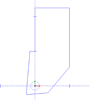
1 In the graphics area, draw the 2D shape of the holder.
At the position of the attachment point of the tool insert, place a dashed circle.
It does not matter which dashed pattern is chosen, just that the circle itself is not solid.
2 To open the Tool Library, do one of the following:
Right-click ![]() CAM Defaults, and click
Tool Library.
CAM Defaults, and click
Tool Library.
Right-click ![]() Turning
Tools, and click Tools.
Turning
Tools, and click Tools.
3 In the Tool Library, select the lathe tool category that you want to modify.
4 In the list on the right side of the dialog box, click the tool that you want to modify, and click Modify.
(If you are creating a new tool, just select the category, and click Add.)
5 In
the Create/Modify dialog box,
click Edit Tool Holder.
6 In
the Tool Holder Definition dialog
box, select the radio button for Custom.
7 Click Pick Geometry.
The Tool Holder Definition dialog box hides to allow you to select geometry from the graphics area.
8 In the graphics area, click and drag a window around the entire drawing to select the holder geometry.
9 Right-click anywhere
in the Workspace, and
in the shortcut menu, click ![]() OK.
OK.
The holder geometry is now assigned to the selected tool.
Click
OK
to save the changes and return to the Tool Library.