In this Topic Show
The Current Settings dialog box controls various machine and posting parameters. You can define and modify the machines that you use in order to create proper NC programs and simulation. Setting these options to reflect what the machine is capable of is an important part of properly setting up the software. The settings in this dialog box apply to the selected machine and are saved when you click OK. When you click Save As Default, the machine and the current settings are used as the default for each new Wire EDM Job that is created.
This topic describes the Current Settings Default dialog box parameters that become available when a Wire EDM machine is selected in the Machine Parameters section. To learn about all other machine types, view the Current Settings Default Dialog Box topic.
To access the Current Settings Default dialog box to set the system defaults (for new files):
To access the Current Settings Job dialog box and update settings for the current job only:
The Machine Parameters page of the Current Settings is used to select a default machine, modify an existing machine, or to create a new machine. All of these actions are performed using the Machine group as explained next. When you select a machine in the Machine group, all of the parameters contained in the Current Settings dialog box (for all pages) pertain to that machine.
Make - displays the make/name of the currently selected machine. To update the Current Settings dialog box with all of the parameters for a machine, click the arrow, and select a machine. You can then modify the parameters as needed. These parameters are saved when you click OK. To use the current selection and settings for all new files, click Save As Default.
Type - displays the machine type that is defined during machine creation.
Add - opens the Add/Modify Machine dialog box for you to create a new machine as explained in the next section.
Delete - removes the selected machine. A dialog box is displayed, click Yes to delete the selected machine.
Modify - opens the Add/Modify Machine dialog box for you to change the name of the machine. For Milling, Laser, Plasma, or Waterjet machines only, the Type of machine can also be changed (to any other of these four types).
Save As Default - saves the current machine and all parameters as the default machine for all new files. (This determines the default Machine that displays in the Machining Job dialog box when the Job Type is set to Wire EDM.)
4 Axis Output
The 4 Axis Output group is only shown when a Wire EDM machine is selected. Select the Type from one of the two following options to define the output type of 4 Axis Wire EDM programs.
XYUV - outputs the NC program in XYUV format where XY is the lower guide output and UV is the upper guide output. This output format is generally supported by more machines than the 4 Axis Entities format. Select this format if your machine does not support 4 Axis Entities.
4 Axis Entities - outputs the NC program using G02, G03 codes for arc moves. Most machines do not support this format, but it can be used for any Wire EDM machine that does.
Machine Name - type the name of the machine you are creating.
Type - set the machine type: Milling, Laser, Plasma, Waterjet, Lathe, or Wire. Select Wire to show all of the remaining parameters as explained in this topic. (For information on other machine types, view the Current Settings Default Dialog Box.)
Machine Make - sets the machine manufacturer for Wire EDM machines only.
Use Cutting Conditions
 Select the check box when using the Cutting Conditions Database that is
provided with the software. You can then click Select to assign the appropriate
database file to the machine.
 Clear the check box when not using the Cutting Conditions Database. The
Select option no longer displays. When you clear the check box, the Link
to Database check box in the Wire EDM Wizard becomes disabled for all
features.
Select - displays the Open dialog box for you to select the appropriate Cutting Conditions Database for your machine. Be aware that there are three filter types, Generic Database (.EDMCC), Sodick Database (.SODCC), and Brother Database (.BROCC). The filter option displays in the lower-right corner of the dialog box, next to File Name. If you are not finding the database that you are looking for, click the arrow and select the appropriate filter type for your machine.
Use CT Expert
 Select the check box when using the Cutting Technology Expert database
for Charmille machines only. You can then click CT
Expert to assign the appropriate database file to the machine.
 Clear the check box when not using the CT Expert for Charmille machines.
Use Machining Registers
 Select the check box when manually editing the machining registers for
Agie machines. The four available registers are added to the Cutting Conditions
page of each operation in the Wire EDM Wizard.
 Clear the check box to not allow editing of the machining registers.
Use Submerged Machining
 Select the check box when your Wire EDM programs use submerged machining.
 Clear the check box when your Wire EDM program does not use submerged
machining.
Maximum Arc Radius - determines the maximum radius for arc moves output in the NC program. Type the appropriate value supported by your machine in this box.
The Machine Definition for Wire EDM is currently predefined. You can view the Machine Definition, but you can't update any parameters on the Machine Definition page. All machine parameters are defined by the remaining pages in Current Settings.
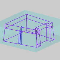
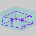
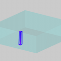
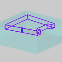
Taper Display Extend
This option determines the system default setting in the Wire EDM Wizard for creating Land and Taper operations.
 Select the check box to extend the graphical display of the wirepath for
each Land and Taper operation to the vertical extents of the feature.
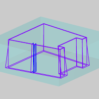
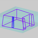
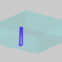
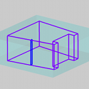
 Clear the check box to turn off the extended taper display. The wirepath
for each operation displays only in the areas they cut as if looking at
the finished part or feature.
 Select the check box to allow the software to output auto threading codes
for machines equipped with an auto threader.
 Clear the check box to not allow auto threading code output.
AWT Minimum Distance - specifies the minimum distance allowed when using Automatic Threading on machines that support it. This is the minimum clearance distance from the part profile.
 Select the check box to output a separate start hole program in addition
to the normal NC program output. You must have the proper Hole Post processor
defined on the posting page.
 Clear the check box when not outputting a start hole program.
Post - displays the Open dialog box for you to locate and select a (.EDMPst) post processor to use for the selected machine.
Hole Post - displays the Open dialog box for you to locate and select a (.HPst) post processor to use for the selected machine.
NC File Path - displays the Browse For Folder dialog box for you to specify the folder in which the posted NC program is stored when created.
Post Info File - displays the Open dialog box for you to locate and select a post processor information file that is machine specific. This option only displays when Command ISO is selected as the Post Output Type.
Program
Number - is the program number as it appears in the posted NC program.
Sequence Start # - designates the starting line number for events in the NC program if the machine is configured to output them.
Sequence # Increment - sets the number added to each subsequent line number for the next line.
Subprogram
Output Subprograms
 Select the check box to generate repetitive subprograms in the posted
NC program, if the post processor is set up to do so.
 Clear the check box when not generating subprograms.
The following two options are only available when the Output Subprograms check box is selected.
Subprogram Start # - sets the first subprogram number used in the NC program.
Subprogram # Increment - if more than one subprogram is generated, this value sets the number added to the previous subprogram number for the next.
Output Cutting Conditions
 Select the check box to allow the Cutting Conditions to be output.
 Clear the check box to not allow Cutting Conditions to be output.
Output Automatic Comments
 Select the check box to allow the automatic comments to be output.
 Clear the check box to not allow the automatic comments to be output.
Output Cuts to Separate Files
 Select the check box to output each operation to a separate file. This
must be configured in the post processor.
 Clear the check box to output the entire program in one file.
Output File Breaks
 Select the check box to output markers in NC program that can be used
to modify or reformat the code after it is post processed. When enabled,
post block 75 is called to output new file header code in the NC program.
This post block requires the post processor to be customized to function
properly.
 Clear the check box to output the NC program without file breaks.
Output Guide Positions
 Select the check box to output the guide positions of the program.
 Clear the check box to not output guide positions.
The Cutting Parameters only display when Sodick AQ325 or AQ537 machines are selected.
When you are finished with all Current Settings, click OK to save all of the settings with the selected machine. After you have defined all of your machines in the Current Settings Default, they are then available for all new CAM Jobs and can be selected per job from the Current Settings Job. To learn more, view the links listed next.