Pocketing - Plunge Location
In this Topic ShowHide
Introduction
This topic explains how to define the plunge location for pocketing
toolpaths. This information applies to both the Plunge Point for Mill
2 Axis Pocket operations, and the Drill Tip Positions for the Mill 3 Axis
Advanced Rough operations.
Purpose
The purpose of setting a plunge location is to allow you to define where
the tool plunges into a pocket, for example, after drilling a hole to
create an entry point for the roughing tool that clears the material from
the pocket.
IMPORTANT: You
can alter the plunging location for a pocket when
the plunge move is inside the part. It is not used to change plunge
locations that are outside of the part (it is not a start point control).
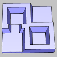
The
Part |
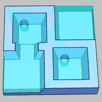
The
Stock with Pre-drilled Holes |
 |
 |
Using Plunge Points
After creating either a 2-axis Pocketing operation or the 3-axis Advanced
Rough operation, you can use the Feature
in the CAM Tree to assign a plunge point or drill tip positions to
these operations, respectively.
Important Notes
- The geometry (point) assigned to the Plunge Point or Drill Tip
Positions item must be placed at or below the same depth as the feature
or cut depth
- Plunge points can be used for open or closed pocketing, but open
pockets must contain more than one region (or group) for the point
to be used (you cannot change the plunge location when it is outside
of the part)
- For the 3 Axis Advanced Rough operation, when there is more than
one region, you can assign one point for each region (the point that
is closest to the start of each region is used for that region)
- For 2 Axis Pocket operations, you can assign one plunge point per
feature
- When using multiple depths and ramping with the 2-axis Advanced
Pocket pattern or the 3-axis Advanced Rough operation, you can set
the toolpath to use ramping below the defined plunge location
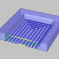
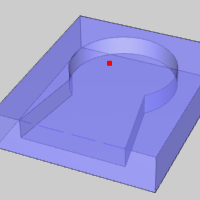
Closed Pockets
With closed pockets you can assign the plunge point anywhere inside
the pocket, with the exception that it must clear the perimeter (walls)
by a distance that is greater than the tool radius, or the point is ignored
in the toolpath calculation.
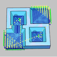
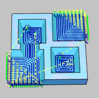
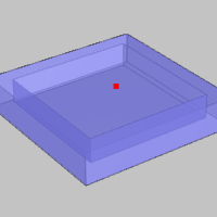
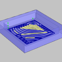
The next two images show pocketing toolpath without a plunge location
assigned. The plunge location for these pockets can be modified as desired,
because the plunge location is inside of the part.
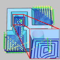
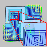
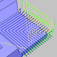
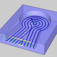
After assigning a plunge point at the same depth as the feature, the
toolpath is calculated to update the plunge location.
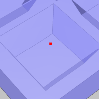
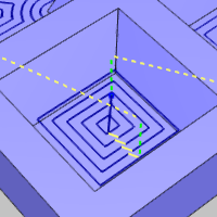
The toolpath now uses the assigned plunge location.
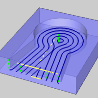
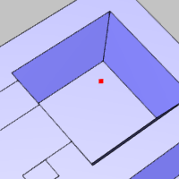
Open Pockets
Plunge points can only be defined for open pockets when there is a plunge
move that is inside the part. In other words, there must be more than
one region or group to use a plunge point with an open pocket.
IMPORTANT: When
setting a plunge location for open pocketing, you can first compute the
toolpath without assigning the plunge location. This way you can see if
there is more than one region (plunge moves inside of the part). If more
than one region exists, then you can modify the plunge location inside
the part geometry.
The following images show open pockets that contain only one region.
Assigning a plunge point for this scenario does not change the toolpath,
because the plunge moves are outside of the part (there is only one region).
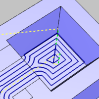
The next images show open pockets that have plunge moves inside of the
part (there is more than one region). For this scenario, we can change
the plunge location that is inside the pocket.
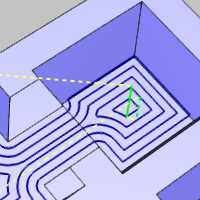
After assigning a plunge point at the same depth as the feature, the
toolpath is calculated to update the plunge location inside the pocket.
Tip - Multiple Depths and Ramping Below the Plunge Depth
When using multiple depths and turning on one of the ramping options
(ramp or spiral), you can assign a plunge location to the bottom of the
pre-drilled hole, and the toolpath is created with a standard plunge move
into the hole, but then uses the specified ramping move for all depths
below the plunge location.
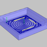
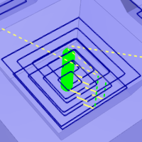
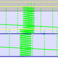
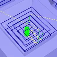
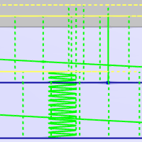
The following is an example toolpath with two depth steps and the spiral
ramping option turned on with no plunge location assigned. Notice the
spiral ramp move is applied to all depths from the top to the bottom of
the feature.
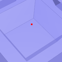
A plunge location is then assigned at the bottom of the first depth
cut as shown next.
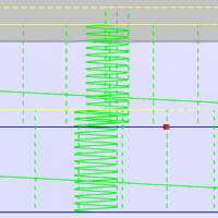
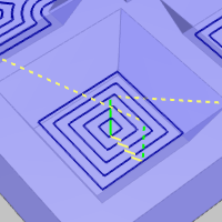
After computing the toolpath with the assigned plunge location, the
spiral ramping move is only applied below the specified plunge location.
The first plunge move is a direct plunge into the pre-drilled hole location.
Final Note About Expected Result
Without Adaptive Roughing
When you are using any cut pattern other than adaptive, the toolpath
remains the same as before the plunge location is assigned. In this case,
the toolpath plunges using the new location, and then feeds directly to
the start of the toolpath.
With Adaptive Roughing
When you are using the adaptive roughing option, assigning a plunge
location may change the entire toolpath, using the new plunge location.
Related Topics
The 2 Axis Pocket Operation
The
3 Axis Advanced Rough Operation
Milling
Features in the CAM Tree

 Feature 2 Axis

 Geometry
 Default Chain Start Point
 Pocket
 Geometry
 Drill
Tip Positions
Drill
Tip Positions Gouge
Check Surfaces
Gouge
Check Surfaces