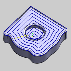
This topic provides some images of the results created using the Equidistant operation with and without Drive Curves selected.
The following image shows an Equidistant operation without using Drive Curves. Notice that the offset pattern is created using the outer boundary of the model.

The following images show the result of selecting a single Drive Curve. Notice that the offset pattern is created using the Drive Curve geometry.
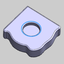
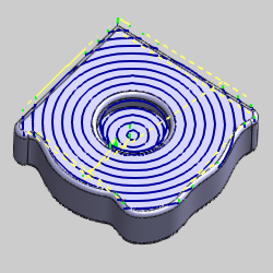
The following images show the result of selecting two Drive Curve chains. Notice that the offset pattern now morphs between the two Drive Curves.
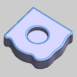
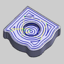
The following image shows the result of using Step Direction Left without selecting any Drive Curves. The Number of Cuts Left is set to zero.
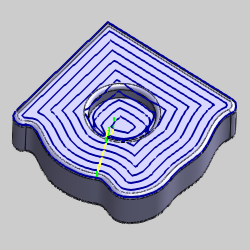
The following image shows the result of using Step Direction Right without selecting any Drive Curves. The Number of Cuts Right is set to zero.
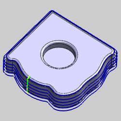
The following images show the result of using Step Direction Left when selecting Drive Curves. The Number of Cuts Left is set to zero.

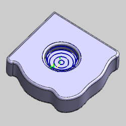
The following images show the result of using Step Direction Right when selecting Drive Curves. The Number of Cuts Right is set to zero.

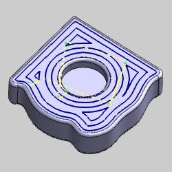
Equidistant Operation Parameters