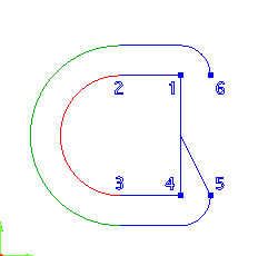
Create Lines by Joining Entities
Example
- Click on the Line Join
icon on the CAD toolbar or
select the Join function from
the Lines menu.
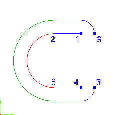
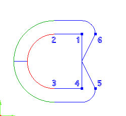
Left click on the point labelled "1"
Rest the cursor over the end of the
red arc labelled "2" to see a preview of the line that will
be created.
Left click on the end of the arc to
create the line between points "1" and "2".
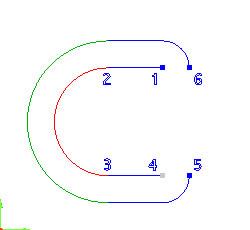
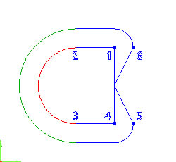
Next, left click the end of the red
arc labelled "3".
- Rest the cursor over the point labelled "4" to see a
preview of the line that will be created.
- Left click on the point to create the line.
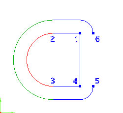
- Left click on the point labelled "4".
- Left click on the point labelled "1".
- A line is created between "1" and "4".
- Left click on the point labelled "5".
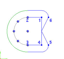
- Hold the SHIFT key on the keyboard and then left click on the line
between points "1" and "4". Snap locations
will appear on the selected line.
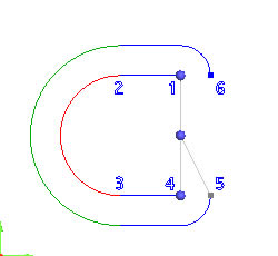
- Left click on the snap location in the center of the line to create
the line.
- Left click on the point labelled "6".
- Hold the SHIFT key on the keyboard and then click on the line between
points "1" and "4". Snap locations will appear
on the selected line.
- Left click on the snap location in the center of the line to create
the new line.
- Hold the SHIFT key on the keyboard and left click on the red arc
segment. Snap locations will appear on the selected arc.
- Left click on the snap location that appears at 9 o'clock on the
red arc (far left).
- Hold the SHIFT key on the keyboard and left click on the green
arc segment. Snap locations will appear on it.
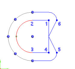
- Left click on the snap location that appears at the far left (9
o'clock) position on the green arc to create a line segment.
- To end the function, right click in the graphics
area and then choose Cancel
in the pop-up menu or click Cancel
in the Data-CAM Tree Manager.
TIP: During
the use of this function, you can remove existing selections by clicking
the selected entity.