Create a Hole Pattern
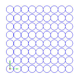
Example 1 (Grid Pattern - Enter Method)
- In the File menu, click
New.
- In the Other menu, click
Hole Pattern. The Hole Pattern
parameters display in the Data Entry tab of the Data-CAM Tree Manager.
- Click Grid.
- In the Width box, type
4.000,
and in the Height box, type
4.000.
- In the Hole Diameter box,
type 0.375.
- Click Break. This creates
each hole of the pattern as a separate entity. When Break is not selected,
the entire Hole Pattern is created (and can be selected) as a single
entity.
- Under Number of Holes,
in the X box, type 9.
- In the Y box,
type 8.
- The Origin method is set
to Enter with the XYZ
values all set to 0.000.
The default Origin location,
Bottom, sets the origin to
the bottom-left corner of the pattern. The origin of the pattern is
placed at the specified XYZ location (when using the Enter method).
To create the hole pattern as shown in the CAD preview, click
OK.
To fit the geometry to the screen, press F.
(Or, in the View menu, click Fit All.)
To finish the function, click Cancel.
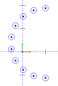
Example 2 (Circular Pattern - Pick Method)
- In the File menu, click
New.
- In the Other menu, click
Hole Pattern. The Hole Pattern
parameters display in the Data Entry tab of the Data-CAM Tree
Manager.
- The default, Circular,
is already selected.
- In the Start box, type
90.000, and in the End
box, type 270.000.
- In the Dia. box,
type 3.000. This defines the
diameter of the Hole Pattern (not the holes).
- In the Hole Diameter box,
type 0.325. (This defines
the diameter of each hole created.)
- Under Number of Holes,
in the X box, type 10.
(The Y value is unavailable for the Circular type.)
- In the Origin
group, click Pick.
(This means that you pick the origin of the Hole Pattern in the graphics
area.)
Below Origin, click
Center. This sets the origin
to the center of the pattern.
Point to any location in the graphics area, and click to create
the Hole Pattern. When using the Pick method, a new Hole Pattern is
created is time that you click in the graphics area.
To finish the function,
click Cancel.
Usage Tips
When using the Pick method (explained in Example 2), you can click an
arbitrary location in the graphics area to create the pattern. You can
also click the snap point of an existing entity in the graphics area to
set the origin of the Hole Pattern when using Pick. To learn more about
selection methods, view Selection
Mode.