In this Topic Show
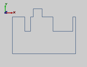
The Stretch function is used to modify wireframe geometry chains by selecting one or more entities and then moving them, thus stretching the connected entities to accommodate the move. You can apply the information in this example to your own parts, or if you need help creating geometry to use with these examples, view the CAD_Tutorials.
1 In the Utilities menu, click Stretch.
The Stretch parameters are displayed in the
![]() Data Entry tab.
Data Entry tab.
2 To stretch to an arbitrary location, click Drag.
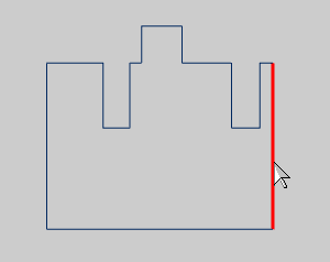
3 To modify a single entity, in the Pick Mode group, select Single Entity. (To modify multiple entities, select Multiple Entities.)
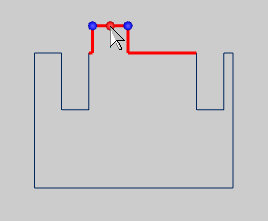
4 In the graphics area, select the entity to move.
 |
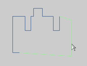
5 The selected entity and the two connected entities are no longer fixed. (When using Multiple Entities, you must press the Spacebar after making the selection.)
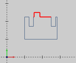
Move the mouse to any location in the graphics area to view the preview of how the entities are stretched. When you have reached the desired location, click to place the selected entity.
Drag Preview |
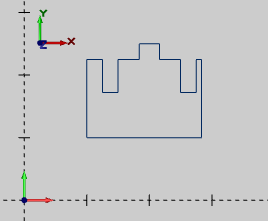
The Result |
 |
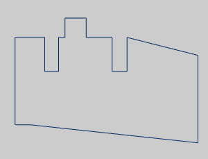 |
TIP: This example used the default Stretch Direction option of No Restriction. You can limit the dragging direction by using the Horizontal/Vertical options. This limits the dragging to one direction only.
6 To exit the Stretch function, click Cancel.
1 In the Data Entry tab, click Delta.
2 In the Pick Mode group, click Multiple Entities.
3 In the End group, in the X box, type 0.500.
4 In the graphics area, select the entities to move, and press the Spacebar.
Press Enter. (You can also press OK in the Data Entry tab. If you continue to press Enter or click OK multiple times, the move is performed each time. For this example, if you pressed Enter three times the entity would move 1.500 inches.)
Geometry Selection |
The Result |
 |
 |
The selected entities were moved, from their current location, 0.5 units in the positive X-axis direction.
5 To exit the Stretch function, click Cancel.
1 In the Data Entry tab, click Sketch/Enter.
In the Pick Mode group, click Multiple Entities.
2 In the End group, select Enter.
In the X box, type 2.000, and in the Y box, type 2.500.
3 In the graphics area, select the entities to move, and to accept the selection, press the Spacebar.
Geometry Selection |
 |
4 In the Start group, select Pick, and in the graphics area, you pick the point from which the move starts.
To view the snap points of the line, hold down Shift, and click the entity.
Once the snap points are visible, select the desired point.
The move is then automatically performed.
(You do not have to show the snap points in order to use them. You can click the entity, and the closest snap point is automatically used.)
(Move From) Snap Point Selection |
The Result |
 |
 |
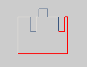
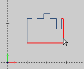
5 The next step is to make the right side the same as the left side. Select the vertical line on the right, select the two connected lines.
To confirm the selections, press Spacebar.
6 In the End group, in the X box, type 3.00, and in the Y box, type 1.00.
Click near the bottom of the vertical line on the right side, and the stretch is automatically performed.
(When you click near the bottom of the vertical line, you are selecting the snap point at the end of the line, which defines the Start point or the Move From location.)
Geometry Selection |
The Result |
 |
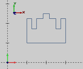 |
7 To exit the Stretch function, in the Data Entry tab, click Cancel.
This concludes the tutorial.