In this Topic Show
The Unwrap function is used to create wireframe entities by unwrapping cylindrical geometry. This topic explains the steps used to unwrap geometry in various scenarios. You can apply the information provided in this example to your own parts.
The General Procedure:
1 In the Utilities
menu, click Unwrap. The Unwrap
parameters are displayed in the ![]() Data Entry tab.
Data Entry tab.
2 Select the Unwrap Diameter. When User Defined is selected, type the diameter of the geometry being unwrapped.
3 Select the Unwrap Rotation Center Axis.
4 In the graphics area, select the geometry to unwrap. (If the Unwrap Center Axis is set to Line, you select the line after selecting the unwrap geometry.)
5 Press the Spacebar
(![]() OK) to unwrap the geometry.
OK) to unwrap the geometry.
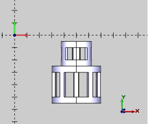
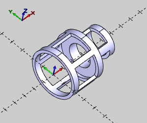
1 The Unwrap function can accommodate various part orientations. When the rotational center of the part is aligned directly on the X-, Y-, or Z-axis, set the Unwrap Rotation Center Axis to the appropriate axis.
For the following example, X Axis is selected.
Example Part with X-Axis Orientation |
 |
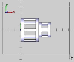
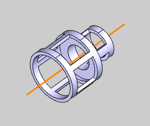
2 You can also draw a line through the rotational center of the cylinder to manually select as the Unwrap Rotation Center Axis. You select the line after selecting the unwrap geometry.
Using a Line for the Unwrap Center Axis |
 |
3 Another way to deal with custom part orientations is to use the User Defined option.
When selected, the Origin and Direction groups become available.
In the Origin group, type X-, Y-, and Z-values to define a point along the Unwrap Rotation Center Axis.
In the Direction group, type the X-, Y-, and Z-values to define the direction from the Origin.
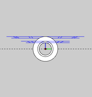
For example, the following image shows the part with the center axis aligned to +X5 (parallel to the Y-axis).
Notice that the Direction values define the direction as parallel to the Y-axis.
|
User Defined Values |
|||
| Origin | Direction | ||
X |
5.000 | X |
0.000 |
Y |
0.000 | Y |
1.000 |
Z |
0.000 | Z |
0.000 |
Notice that the Origin values define a point along the rotational center of the part in the graphics area.
Notice that Direction, X0Y1Z0, is a vector that defines the direction of the rotational center of the part as parallel to the Y-axis.
For this example, the part is oriented along the X-axis as shown in Part 1.
1 In the Utilities menu, click Unwrap. In the Unwrap Diameter group, click Automatic. This is the default setting.
2 In the Unwrap Rotation Center Axis group, select X Axis.
3 In the graphics area, drag a window to select the entire part.
Press the Spacebar to confirm the selection.
|
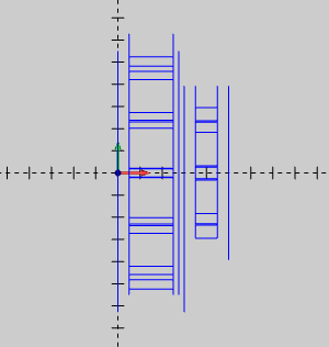
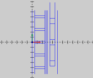
4 The geometry is unwrapped using the actual diameter of each section of the part.
In the next image, the part is hidden to better show the unwrapped geometry.
|
5 To exit the Unwrap function, in the Data Entry tab, click Cancel.
This example uses the same part and orientation as in Part 2. For this example, the geometry is unwrapped using the greatest diameter of the part which is 4 units.
1 In the Utilities menu, click Unwrap. In the Unwrap Diameter group, select User Defined.
2 In the User Defined box, type 4.00.
3 In the Unwrap Rotation Center Axis group, select X Axis.
4 In the graphics area, drag a window to select the entire part.
To confirm the selection, press Spacebar.
|
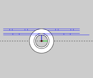
5 The geometry is unwrapped using the User Defined value of 4.00 units.
In the next image, the part is hidden to better show the unwrapped geometry.
|
6 To exit the Unwrap function, in the Data Entry tab, click Cancel.
This concludes the tutorial.