This tutorial will illustrate how to nest parts with holes and dadoes.
You will also learn how to utilize the Nesting Layer Manager to assign
layers that don't fall into the recommended naming convention, but that
need to be assigned into the holes, dadoes, CAD, or ignored groups to
be handled as such.
The first step of any nesting program is to have the parts in mind that we want to nest and create a Nesting Job. In this case we will be opening a file first and then creating a job inside of that file.
1 Open
the Hole_Dado_Tutorial.bbcd file from the C:\BobCAD-CAM Data\BobCAD-CAM
V**\Examples folder. Note that when creating a nest, the original
orientation of the parts in the CAD window is not important. The
parts in this file have been moved off to left because we will be setting
up our sheet in the X+,Y+ quadrant. This will make things a little easier
to see once the nest has been completed.
2 In
the ![]() CAM Tree tab of the Data-CAM Tree Manager, right-click
on
CAM Tree tab of the Data-CAM Tree Manager, right-click
on ![]() CAM Defaults and select New Job to launch the Nesting
Wizard.
CAM Defaults and select New Job to launch the Nesting
Wizard.
3 Select
Nesting as our Job Type and then click the Nesting Wizard button.
When it comes to picking geometry you can either select geometry that is already open in your CAD window, load geometry from existing files that have not yet been open, or a combination of both. In this case, we will use a combination.
1 Click
the Select Geometry button. The Nesting Wizard hides, and selection
mode is activated.
2 Select
the  icon at the top of your screen or press Ctrl+A
on your keyboard to select all of the geometry in your CAD window at the
same time.
icon at the top of your screen or press Ctrl+A
on your keyboard to select all of the geometry in your CAD window at the
same time.
IMPORTANT: Simultaneous selection of all geometry at once is not recommended unless you are absolutely sure the geometry is clean. If you are not sure the geometry is clean, use a chain selection method to pick one chain at a time. Find out more about chain selection here.
3 Once
all of the parts are highlighted, press the spacebar on your keyboard,
or right click in the graphics area and click OK, to confirm the part
selection.
4 The
Nesting Wizard returns, and the four separate parts are listed in the
Part List area.
|
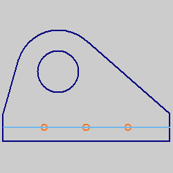
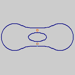
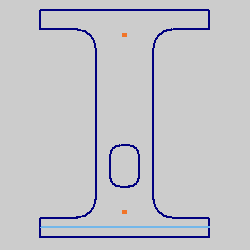
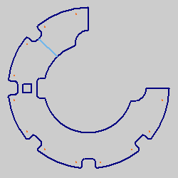
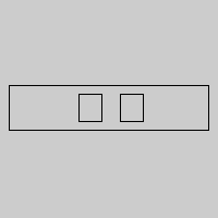
5 Notice
that there are three colors present in the previews. These represent the
various operational assignments of the geometry. They are as follows:
A Profile
B Hole
C Dado
Now that we have selected the parts from the CAD window, we will import the other files needed for the nesting job.
1 Click
the Load Files button and navigate to the C:\BobCAD-CAM Data\BobCAD-CAM
V**\Example folder.
2 Click
on 8inch_Dadoes_Holes.bbcd to highlight the file.
3 Hold
Ctrl on your keyboard and click on 8inch_Dadoes_Holes2.bbcd to highlight
that file as well.
4 Click
Open to load the two files and launch the Nesting Layer Manager.
To have the system automatically assign the proper operations to hole and dado geometry, each type of geometry needs to be separated to a layer of the same name. When importing files whose layers do not align with that naming convention, using the Nesting Layer Manager to assign each layer to the proper operational group becomes necessary. Note how the groups are arranged in the example below.
File Name |
Profile Layers
|
Hole Layers
Dado Layers
Ignore Layers
|
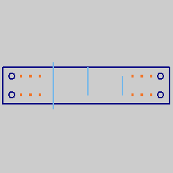
1 With
both files already loaded, you will be able to see both files listed in
the File Name group. By default the first file is highlighted and all
of its layers are visible in the Profile Layers group. Any layer that
stays in the Profile Layers group will be handled as a profile. Take a
moment to click on each layer name to see the associated preview to the
right in order to decide to which group each layer should be assigned.
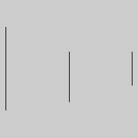
CAD |
.5 Dia |
Dadoes |
1.5 Dia |
Dimensions |
|
|
|
|
|
NOTE: Notice the preview for the dimension layer is blank. Dimensions are not valid nesting geometry and, as such, will not be shown in the preview.
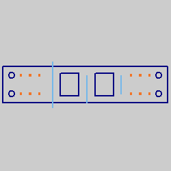
2 Judging
by the previews, it looks like the only thing that should be under the
Profile Layers, is the CAD layer, which contains the outer profile of
the part. We now need to assign the other layers to the proper groups.
Rather than do this manually, click the Auto Assign Layers button below
the File Name group.
3 Notice
that the layers are not all under the Profile Layers group any longer.
Notice in the Log below the following information has been generated:
******************************************************
Layers with Open Chains to Dado: On
Hole Layer Filter: On
MinDiameter: 0.0000
MaxDiameter: 4.0000
8inch_Dadoes_Holes.bbcd
.5 Dia -> Drill Hole Layers
Dadoes -> Dado Layers
1.5 Dia -> Drill Hole Layers
******************************************************
This tells us which layers have been moved, and to which groups the have
been moved to. The moves will also be evident in the groups themselves.
4 Notice
in the Profile Layers group we have two layers. Since we will not be cutting
the dimensions, we will move that layer to the Ignore Layers field. Drag
the Dimensions layer to the Ignore Layers group.
5 We
have two layers in the Holes Layers group. Now that we are looking at
each a little closer, 1.5 inches is too large of a hole to be handled
as a drilling operation. We will need to move the 1.5 Dia layer to the
Profile Layers group so we can handle that geometry with a profile cut
instead. Drag the 1.5 Dia layer from the Holes Layers group and
into the Profile Layers group.
For this second file we will use the Holes Layer Filter so that we don't need to adjust our 1.5 Dia layer after we use the Auto Assign Layers option.
1 Click
on the 8inch_Dadoes_Holes2.bbcd in the File Name group and take a moment
to click on each layer name to see the associated preview to the right
in order to decide to which group each layer should be assigned.
CAD |
.5 Dia |
Slots |
1.5 Dia |
Dimensions |
|
|
|
|
|
2 In
this case you can see that the content in the layers, along with the layer
names themselves are almost identical to the first part, save for a couple
of small variations. In this file as well, we have a 1.5 Dia layer that
we will want to have handled as a profile. We will prepare for that prior
to using Auto Assign Layers with the Filters.
3 At
the bottom left of the Nesting Layer Manager, notice we have a Filters
group with two check boxes selected by default. In this instance, we will
utilize the Holes Layer Filter option. Since the holes we want to keep
in the Profile Layers group are 1.5 diameter, enter 1.0000 in the Max
Diameter field of the Holes Layer Filter option.
4 Click
the Auto Assign Layers button below the File Name group.
5 Notice
that our 1.5 Dia layer has remained in the Profile Layers group thanks
to our filter.
6 Drag
the Dimensions layer into the Ignore Layers group.
7 Click
OK.
Now that the parts are all loaded, and the layers have been organized, we will set some basic part parameters.
1 In
the ![]() Part Geometry page, notice
that we now have Part 5 and Part 6 loaded in the part list. Take a moment
to click on each of these to see the associated preview and their color
assignment.
Part Geometry page, notice
that we now have Part 5 and Part 6 loaded in the part list. Take a moment
to click on each of these to see the associated preview and their color
assignment.
Part 5 |
Part 6 |
|
|
2 Click
Next>> to continue to the ![]() Part
Parameters page.
Part
Parameters page.
3 Fill
out the part quantities to match the following values.
Part Name |
Quantity |
Part 1 Part 2 Part 3 Part 4 Part 5 Part 6 |
: 7
: 7 : 2 : 1 : 2 : 2 |
With the Part Parameters set, we will need to adjusting settings for the operations themselves.
1 Click
on the ![]() Default Profile in the
tree to the left of the wizard and set the Total Depth value to 1.0000.
Default Profile in the
tree to the left of the wizard and set the Total Depth value to 1.0000.
2 Click
on the ![]() Rough in the tree under Default Profile. Change
the Diameter value of the default tool from 0.5000 to 0.3750.
Rough in the tree under Default Profile. Change
the Diameter value of the default tool from 0.5000 to 0.3750.
3 Click
on ![]() Leads under the Default Profile
to jump to the Leads page.
Leads under the Default Profile
to jump to the Leads page.
4 Select
the Circular option for the Lead-in.
5 Set
the Length value in the Line group to 0.1875 and the Radius value in the
Arc group to 0.1875 as well.
6 Click
on the ![]() Default Hole in the tree
to the left of the wizard and set the Total Depth value to 1.0000.
Default Hole in the tree
to the left of the wizard and set the Total Depth value to 1.0000.
7 Click
on the ![]() Rough in the tree to the left of the wizard under
Default Dado.
Rough in the tree to the left of the wizard under
Default Dado.
8 Change
the value for Diameter from 0.5000 to 0.2500 to set our dado tool to the
correct size.
9 Click
on ![]() Leads under the Default Dado
to jump to the Leads page.
Leads under the Default Dado
to jump to the Leads page.
10 Select
the Parallel option and then click Compute at the bottom right of the
wizard.
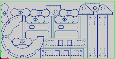
Now that the nest has been generated, we will want to make sure all the parts quantities fit on the sheet.
1 In
the CAM Tree, right-click on ![]() Sheets and select Show Summary. Here we can see we have
three leftover parts. We will attempt to adjust the result to fit the
others on the sheet as well.
Sheets and select Show Summary. Here we can see we have
three leftover parts. We will attempt to adjust the result to fit the
others on the sheet as well.
2 Click
OK at the bottom of the Nesting Summary to close it.
Now that the nest has been generated and we can see there are a few parts that have not been fit, we will try to adjust a setting to get a better result.
1 In
the CAM Tree, right-click on ![]() Nesting Job and select edit to launch the Nesting Wizard again.
Nesting Job and select edit to launch the Nesting Wizard again.
2 Click
![]() Nesting Parameters in the tree to jump to the
Nesting Parameters in the tree to jump to the ![]() Nesting Parameters page.
Nesting Parameters page.
3 Click
the Other Options button to launch the Other Options dialog box.
4 Select
the check box for Best Nesting Direction and click OK to finalize changes
and close the Other Options dialog box.
5 Click
Compute at the bottom right of the Nesting Wizard.
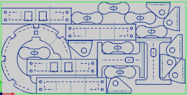
Now that the nest has been regenerated, we will want to check to see if the change we made to the Nesting Parameters has helped eliminate leftover parts.
1 In
the CAM Tree, right-click on ![]() Sheets and select Show Summary. Here we can see we have
no leftover parts.
Sheets and select Show Summary. Here we can see we have
no leftover parts.
2 Click OK at the bottom of the Nesting Summary to close it.
Now that the nest has been generated and all the parts fit on the sheet, we will check the simulation to visualize the machining order prior to posting the code.
1 Right-click on the Nesting Job and select Simulation
to enter into the simulator to check the final result. Learn more
about the simulation here.
Once the nested result has been finalized it will be time to produce
the code to send to the machine.
1 In
the CAM Tree, Click the plus symbol next to ![]() Sheets
to show its contents.
Sheets
to show its contents.
2 Click
the plus symbol next to ![]() Sheet-1
to show its contents.
Sheet-1
to show its contents.
3 Right-click
![]() Sheet-1-1 under the main Tutorial sheet type and
select Post Sheet.
Sheet-1-1 under the main Tutorial sheet type and
select Post Sheet.
4 The
code is posted in the Layer-UCS-Post Manager.
5 Right-click
on the code in the Layer-UCS-Post Manager to select Save As or Edit CNC.
With this method, you can either save to a particular file location or
to open in Predator Editor respectively.
This concludes this tutorial.