In this Topic Show
Release Date: August 2, 2017
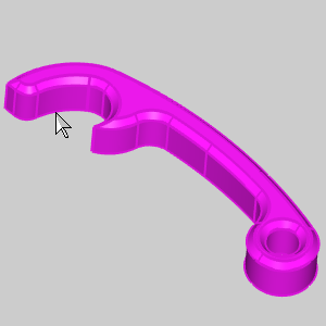
BobCAD-CAM’s Version 30 release has brought with it some incredibly powerful tools to add to your CAD-CAM arsenal. We have made some amazing improvements on geometry selection, how to program your part, and now, even give you a Toolpath Editor to give you the control to edit anything you want about the whole operation, a portion of the operation, or even a single entity of the overall operation. This is a release you really need to see to believe. Schedule a one-on-one demonstration today!
Users now have the ability to handle the licensing of their software without ever having to make a phone call, whether they have internet or not. With new email activation, the user can simply:
1 Download
the request file from their PC without internet connection.
2 Emailing
in the request file from a PC with internet connection.
A license response will be sent back to the user. This new control allows
all license management to be handled by the end user directly at any time,
even outside of BobCAD-CAM office hours.
Introduced by popular demand, we now offer Network Licensing! In many cases, programmers move from station to station and need to be able to have their licensed software available at any one of those stations. In the past, that would require purchasing a licensed copy of the software for each station they may have to work from. With Network Licensing, those licenses are stored on the server and available on any connected station. Now, no matter how many stations are available, licenses only need to be purchased based on the number of stations that may need to be active at once.
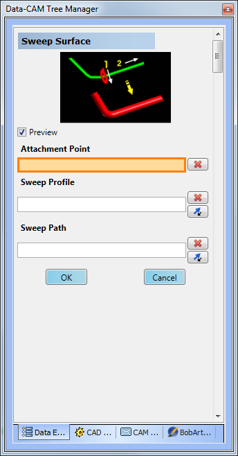
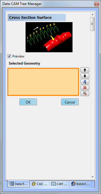
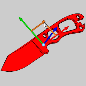
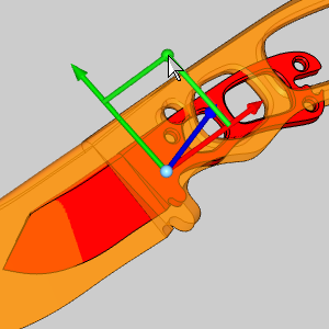
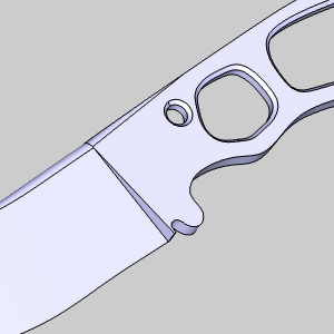
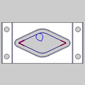
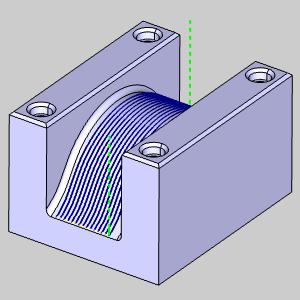
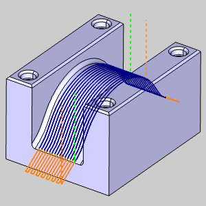
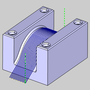
Updates have been made to many of the CAD functions that require the selection of other geometry. Many of the CAD functions require picking other geometry to perform the function; Subtract this from that, or, use this as my Attachment Point, this as my Sweep Profile, and this as my Sweep path are examples. In either case, the order of the selections plays a big role in the result, and, in the past, getting the order wrong would usually result in canceling the function and reopening the function, just to try again. With our new and improved interface, we have eliminated these issues with list boxes for the selected geometry. These list boxes have controls to delete geometry or even reverse chains and adjust the order of the selected geometry when necessary. This gives you an unprecedented amount of control over selection of geometry and the result of the function. The Sweep and Cross Section functions are used as examples below.
One of the huge benefits of the new selection aspect of these functions is being able to try different things to see how they affect the preview of the result before finalizing. The Sweep function, for instance, will give different results depending on the Attachment Point being used. With the new selection functionality, you could pick the Attachment Point, Sweep Profile, and Sweep Path to see the Preview, and then, delete only the Attachment Point, in order to pick a different Attachment Point to test another result. The functions with updated picking are as follow:
Surfaces |
Solids |
Planar Extrude Curve Extrude Surface Revolve Sweep Cross Section Skin Offset 3 Edge 4 Edge Multisided Patch Fillet Intersection Curves Break Surface Swung Ruled
|
Fillet Add Subtract Intersect Extrude Boss Extrude Cut Split Shell Imprint |
The Translate function has a handy new feature to use when scaling. In some cases, scaling is needed without a specific value in mind, an adjustment for aesthetics for instance. It is in cases like these, entering different scale values and checking the resulting preview can be a little frustrating, and in situations like these, the Scale Sketch Handle is the perfect solution. Simply click on the scale sketch handle and drag your mouse to adjust the scale where you want it. Click again to set the scale value.
The new Imprint function is perfect for making electrodes and soft jaws, as it does the work of several different functions. Rather than have to extrude a shape, and then subtract a model you have made a copy of, Imprint, in one easy to use function, allows you to extrude a shape, subtract a model from it, and keep the model you are subtracting, so there is no need to even make a copy first.

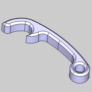
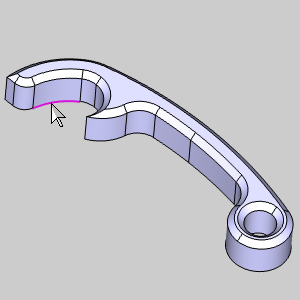
In our BobCAD-CAM V29 release, we introduced a new method of filleting with the option to fillet an entire chain of entities, or multiple chains of entities at once. Not only have we brought that functionality to the Chamfer function, we added another option for both the Fillet and Chamfer to give you three possible methods. The Single Corner Click option allows you to simply hover over the ends of two entities. Once you hover over the entities, you will see a preview of the executable fillet or chamfer. Click, and the Fillet or Chamfer will be created.
Chains |
Single Corner Click |
 |
|
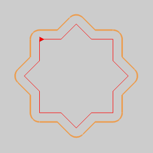
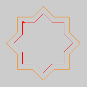
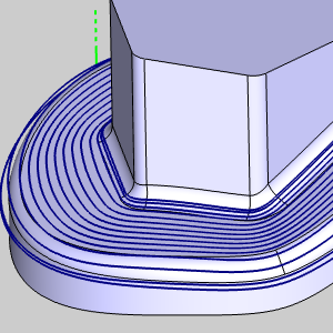
The offset function now has an option for sharp corners. This simple function can save tons of time when offsets are being created. Rather than creating offsets, then delete the arcs and trimming the remaining lines together, the sharp corner offset does this for you!
|
|
|
|
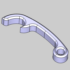
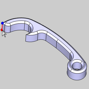
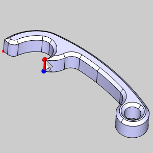
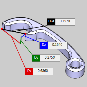
In order to save our customers the step of extracting edges from solids and surfaces in order to be able to pull particular measurements from them, we have altered the Measure One function to allow you to directly measure the edges or vertices on solids and surfaces. You can also select the Pick Solid option to measure an entire solid.
|
|
|
|
|
|
The Measure Two function now allows you to measure snap points on solids and surfaces. There are also graphical representations for each measurement in the graphics area, each of which, can be rearranged.
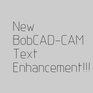
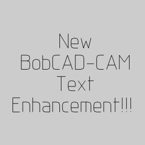
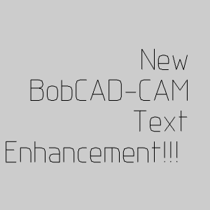
The Text function now has the added benefit of alignment options. When multiple lines of text are being used, you are able to set them to be aligned by, left, center, or right.
Left Aligned |
Center Aligned |
Right Aligned |
|
|
|
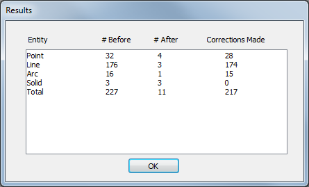
Although they have always been handy to use, the problem with the Fit Arcs, Erase Doubles, and Cleanup/Optimize functions was the fact that, without checking the Entities Summary report, before and after using them, and figuring out the difference in the entity count, you couldn't really be sure how helpful the function was. Now, whenever the Fit Arcs, Erase Doubles, or the Cleanup/Optimize functions are utilized, the user is presented with a report detailing exactly what was accomplished by using the function.
In the previous version of BobCAD-CAM we provided a way to Update All Geometry in your CAM Tree for times when, for whatever reason, something about the geometry associated with your features changes. It was a hit! For this release, we took it a step further. Start Point locations and Chain directions for your Mill 2 Axis features are saved. Now, no matter how many features you took the time to customize the Start Point and Chain Direction for, they can all be updated, and all your customizations will be retained, even if you modify the machining origin location!
Features and Operations can now be locked in order to keep them from
being computed. This is extremely helpful when editing toolpath. Once
an operation has had toolpath edited with the Edit Toolpath dialog, the
operation will have a  icon in front of it, and the name of the operation will appear in red
font. This helps to ensure that the edits to the operation are not accidentally
lost due to recomputing the operation by mistake.
icon in front of it, and the name of the operation will appear in red
font. This helps to ensure that the edits to the operation are not accidentally
lost due to recomputing the operation by mistake.
BobCAD-CAM V30 has improved the Backplot capability by showing tool information and supporting Machine Compensation. By right-clicking on an operation and selecting the Backplot option, users can now see the tool movement, current tool location, orientation, feedrate, start point, and start direction for a single operation directly in the CAD Window. The tool is even offset when using Machine Compensation!
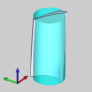
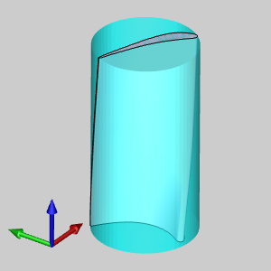
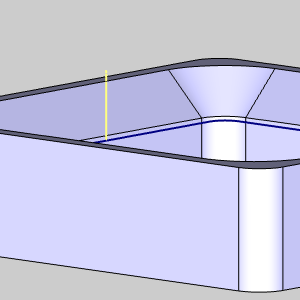
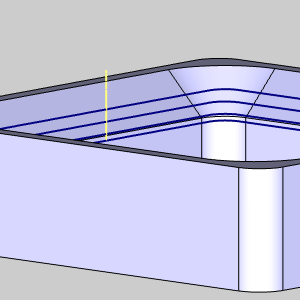
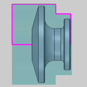
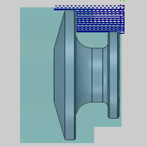
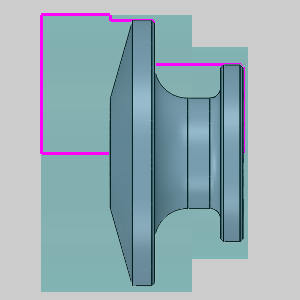
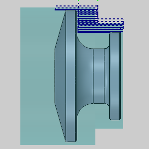
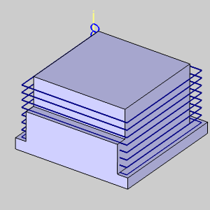
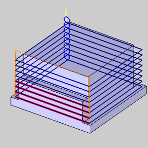
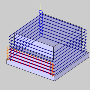
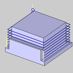
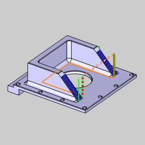
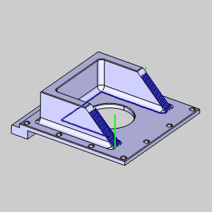
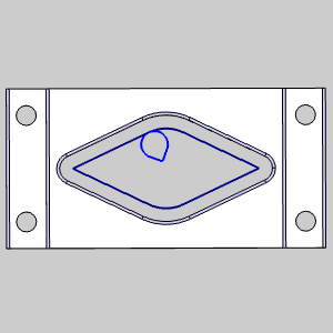
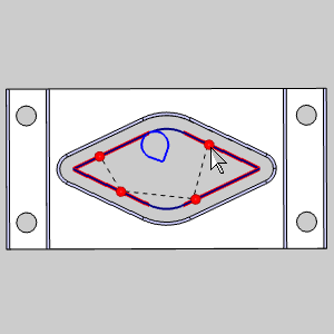
BobCAD-CAM now offers an additional option when defining the size of Cylindrical Stock in the Stock Wizard. In the past, the method to automatically calculate the size and position of your cylindrical stock, was to use a Bounding Box. While in most cases, this worked perfectly, in certain cases, like the one in the example below, the stock would not enclose all of the geometry. To handle these cases, we provide another means of stock calculation called the Bounding Cylinder. This method uses an algorithm to calculate the smallest possible cylinder to enclose the selected geometry.
Bounding Box |
Bounding Box Result |
|
Bounding Cylinder |
Bounding Cylinder Result |
|
|
|
|
|
We now offer customers the ability to encrypt particular portions of a post processor, or even entire post processors to hide data within the post from the general public. This is accomplished in three easy steps: pick your post, pick a name for it, and pick who can use it. The encrypted posts can be set to work with any License ID, particular License ID's, particular Customer ID's, or a combination of particular License, and Customer ID's. Post encryption will be most useful with post containing custom scripted functionality. A BobCAD dealer, or partner may want to encrypt a post they have written for a particular customer. A shop owner may want to encrypt a post that gives his machine custom functionality so an employee won't be able to give it to his buddy in the shop down the street with the same machine. Either way, everyone now has the ability to make their post proprietary if they so choose.
Example of a Post with a portion encrypted
262. Add sign to all coordinate values? n 267. Amount to add to tool # for tool register value?
<--ENCRYPTED BEGIN // The post will work on ANY license ID XRY6MWZE8Q6ERUQH2YJ6R7TNZNC5 HEDGCY2IVQWFETMY42DCDBJYSN90 7SFTPRAQ2IYQ82E8V5ZRFIFHQI79 JMTZJMZU3ZR26JQEV74Y76DGBBWTJXXR2FKDEXRRAZSPTDNVV93S64 RQYY4CYUHGISSPDYN55RYP5WIWEB ET24SPQNZ6GJ3U2YKBJVSNBHTGJCAAC6VTG9FE72FT9EHH6XPKSAC1 <--ENCRYPTED END
273. Output programmable rotary axis codes? y 280. Primary Rotary Axis Modal? y |
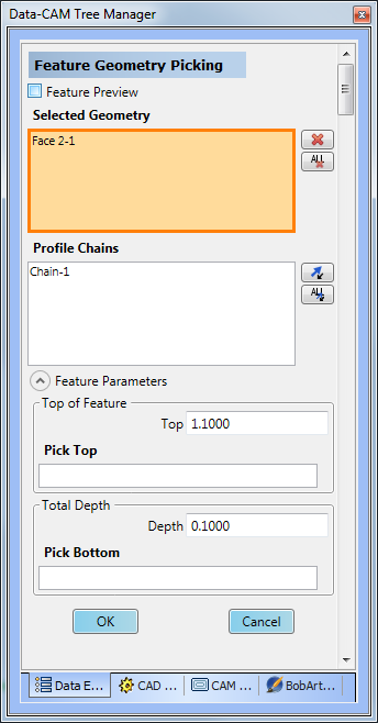
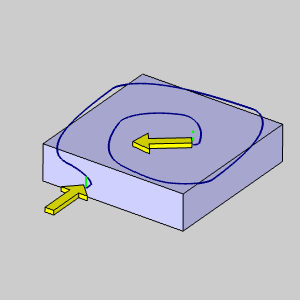
When creating any feature, the first step is to select the geometry. In the past, once geometry was selected, you would return to the Wizard to set the Top of Feature, the Total Depth, and after the feature as created, adjust the chain direction from the CAM Tree. With the new geometry selection method, you can select geometry, set the chain direction, Top of Feature, and the Total Depth all in one dialog.
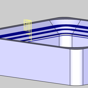
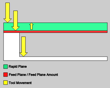
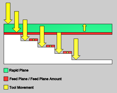
Machinists know; you're only making money when cuts are being made. As such, it is ideal to keep machine moves that aren't cutting to a bare minimum. In the new BobCAD-CAM V30 we now offer a Minimize Tool Retracts option that does just that! When multiple depths are used on the Profile Rough and Finish, Facing, and Corner Rounding operations, this feature will help to eliminate moves back up to the rapid plane and then back down again before the next pass is made. This feature also gives you the power to choose whether to link the passes with a rapid or feed move!
Retracting |
Minimize Retract |
Link with Rapid |
|
|
|
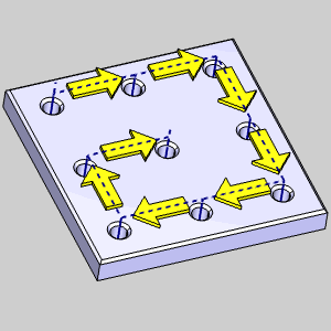
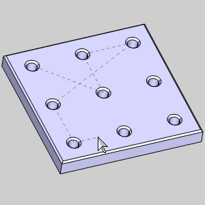
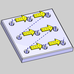
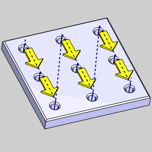
BobCAD-CAM now offers new and improved sequencing options in order to offer lower cycle times. Whether you are creating a Standard Drill, Multiaxis Drill, or even a Cross Drilling feature you will find new, highly effective ways to maximize the efficiency of the sequence. Our Standard Drilling offers X, Y directions, and a Custom Direction option you can define yourself, each of which can be set to a Zig or Zig Zag style sequence. Along with those sequences, we also offer Closest , Pick Order, and Optimized sequences. Closest automatically moves to the next closest hole, Pick Order allows you to select the geometry in the order it is to be machined and Optimized tests many of the sequences along with its own algorithm and gives the result which results in the shortest toolpath. We even go a step further in offering a 'Reverse Each Operation' option to save even more moves. With Reverse Each Operation, drilling features that contain multiple operations, can have subsequent operations track back along the path of the first operation to keep the tool from having to move all the way back to the beginning to start the path again.
|
|||||||||||
Y Direction |
Custom Direction |
Optimized |
|||||||||
|
|
|
|||||||||
The Chamfer operation now gives you the ability to use multiple depths! Selecting the Multiple Depths option allows you to set the Depth of Cut, gives you an option to use a Stepover, gives you control over the order of each of those, and even provides you the option to utilize the Minimize Retracts feature mentioned previously in this document.
Single Depth |
Multiple Depths |
with Stepover |
|
|
|
Operations that offer a Plunge entry method will now offer three different Types of Plunge: Single Depth, Peck, and Fast Peck. These options can be a huge help in saving time and tool life!
Single Depth |
Peck |
Fast Peck |
|
|
|
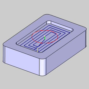
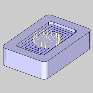
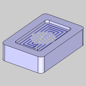
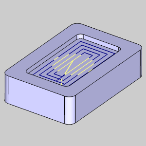
Points is a new toolpath pattern option to assist in copying toolpath and setups whose copies need to have varying distances between them. In the past, there was no way to create a toolpath pattern that did not fit nicely in an array, translation, or rotation. There are many case when a feature, or many features need to have copies that have varying X, Y, Z distances. With the new toolpath pattern option, those variations can be entered in the software as coordinates, or as points selected from the graphics area and BobCAD-CAM will make copies of the toolpath at those locations.
Toolpath to be patterned |
Start Point |
|
|
|
|
Positions |
Result |
|
|
For this release we have added a new Pattern to the Facing operation. Besides the basic Zig and Zig Zag Patterns, you can now choose the new Adaptive Pattern when using the Facing operation. This will allow you to apply a high speed style toolpath that is, both, fast and highly effective.
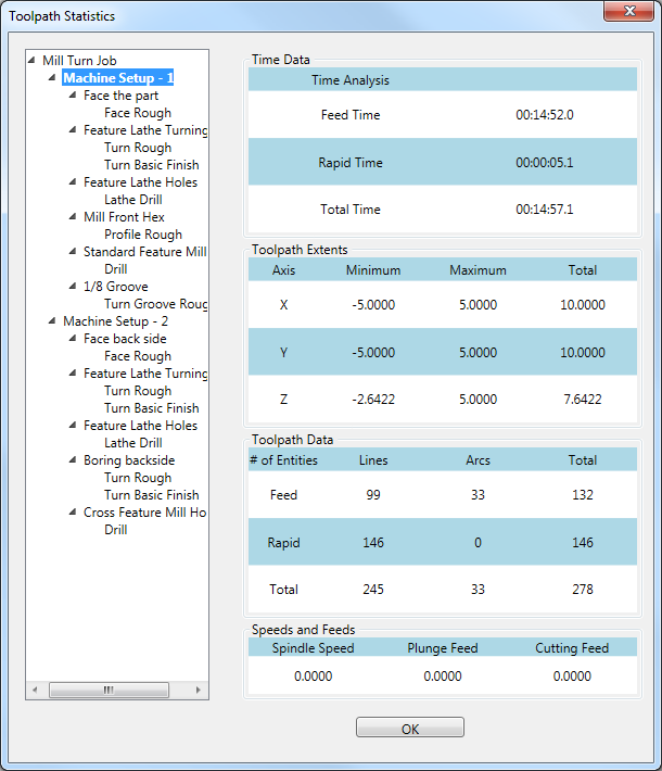
The Toolpath Statistics dialog is now available to give you some useful data about the current toolpath of an existing job. The Toolpath Statistic dialog will give you more information than can be found in the Setup Sheet. While the Setup Sheets provide information like the speeds and feeds of a tool, the Toolpath Statistics provide additional information, like Feed Time, vs Rapid Time, the extents of the toolpath, and even the amount of toolpath entities; Feed entities vs. Rapid entities.
Every now and then, the situation arises that call for the feature geometry to be adjusted. Perhaps during simulation you notice a move that is a little too close, or one that could probably be cut back a little bit to save time. In either situation the result would be the same: Time to adjust the model with CAD tools. Now, new Extensions option will allow you to extend and trim the virtual feature geometry without the need to adjust the actual CAD geometry!! Choose the Start / End option, then enter the values to trim and extend those virtual geometries along the chain. This can all be done without the need to touch a CAD tool!
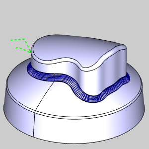
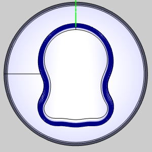
Here, at BobCAD-CAM, we are proud to provide our customers with the best in cutting edge technology (pun intended). However, even when using the best toolpath strategies on the market, you may occasionally create a cutting operation that's perfect, except for one little thing. These situations can be frustrating, since it can be difficult to make the change you want, without affecting the rest of the toolpath you are so happy with. BobCAD-CAM now puts the power in your hands to change anything you want, about any portion, however small, of an operations toolpath with our Edit Toolpath dialog. The Edit Toolpath dialog gives you the ability to:
Allows you to delete toolpath entities and relink the toolpath.
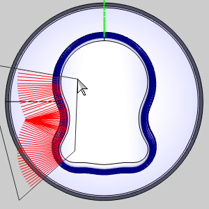
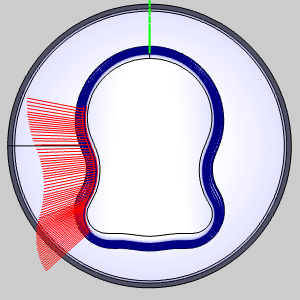
Allows you to create a trimming boundary to trim portions of the toolpath away.
Allows you to move entities of their toolpath and link to the newly located position.
Allows you to draw in your own toolpath and replace entities of the toolpath with this CAD geometry.
Although it is not a command, the Convert to CAD button is listed here as it is extremely helpful when using the Replace command. The Convert to CAD button allows you to select regular toolpath and turn it into CAD geometry. This allows you to create a connection point when adding additional geometry, or it can even be used to turn the toolpath into geometry, to then modify, and turn back into toolpath!!
Allows you to split toolpath entities into multiple segments, this can be used, for example, to later modify a portion of that toolpath, to change the feedrate, or many other uses.
Allows you to modify the feedrate, or feed type.
Allows you to extend the toolpath tangentially by a specified distance.
Gives you the option to modify the tool orientation vector for a selected set of toolpath entities.
This is a new option in the Gouge Check page of the Advanced Rough operation. Unlike other gouge checking options which check for gouges once the toolpath has been calculated, and then trim and relink, this option checks for gouges during the toolpath calculation. You can now check holder with: In Process Stock, or Machining Surface. In Process Stock constantly updates what stock would be remaining as it is removed by the tool. This is extremely helpful, since, as the stock is removed, it is no longer a concern for collision. The Machining Surface option is most helpful when the model extends beyond the stock.
To help create smooth entry and exit options, the adaptive roughing option now offers a Vertical Arc lead when using the plunge entry method for the Adaptive Roughing pattern. This option enables you to utilize vertical tangential arc moves as default lead-in/out segments instead of linear leads.

The Advanced Z Level Finish now offers the ability to use Undercuts! In the past, although lollipops and t-cutter style tools could be used, but the toolpath created would not accommodate undercut areas of the model. Now, you can, not only, cut undercut areas of the model, but even specify to cut only the undercut areas of the model!
|
|
|
|
|
|
With the release of BobCAD-CAM V30, comes a new module for our 3 Axis customer: 3 Axis Premium! The new 3 Axis Premium gives users 8 additional surfaced based toolpaths: Parallel Cuts, Cuts Along Curve, Morph Between 2 Curves, Parallel to Multiple Curves, Project Curves, Morph Between 2 Surfaces, Parallel to Surface, and Flowline. Flowline and blended toolpaths, along with the ability to do undercutting, is just the start. Users that require the best possible surface finishes and demand an unsurpassed amount of control will find this module to be a must have! The new 3 Axis Premium toolpaths will give you the tools you need to stay one step ahead of the competition.
When using an Around Style cut, users now have an option to apply an Adaptive Stepover. This is the same functionality that was a huge help in other 3 Axis toolpaths. With the Adaptive Stepover, steep areas that would normally cause gaps in the toolpath are filled with additional passes to match the consistency of the rest of the toolpath. What would usually require an additional operation to finish, can now be done all in one operation.
|
|
|
|
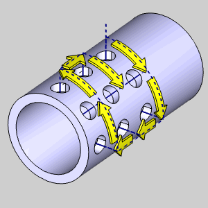
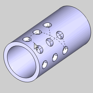
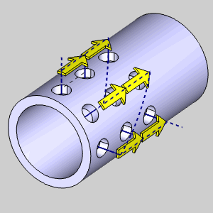
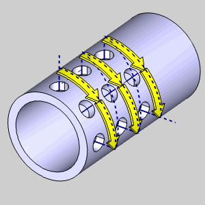
BobCAD-CAM now offers new and improved sequencing options in order to offer lower cycle times. Whether you are creating a Standard Drill, Multiaxis Drill, or even a Cross Drilling feature you will find new, highly effective ways to maximize the efficiency of the sequence. Our Crossing Drilling now offers Along, and Around Rotation Axis sequences, and a Custom Direction option you can define yourself, each of which can be set to a Zig or Zig Zag style sequence. Along with those sequences, we also offer Closest , Pick Order, and Optimized sequences. Closest automatically moves to the next closest hole, Pick Order allows you to select the geometry in the order it is to be machined and Optimized tests many of the sequences along with its own algorithm and gives the result which results in the shortest toolpath. We even go a step further in offering a 'Reverse Each Operation' option to save even more moves. With Reverse Each Operation, drilling features that contain multiple operations, can have subsequent operations track back along the path of the first operation to keep the tool from having to move all the way back to the beginning to start the path again.
Cross Drilling |
||
Closest |
Pick Order |
Along Rotation Axis
|
|
|
|
|
|
|
Around Rotation Axis |
Custom Direction |
Optimized |
|
|
|
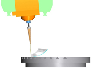
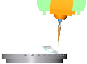
The rapid distance, including the feed distance, can be applied in the tool plane instead of the tool axis plane. This option can be used for machining with undercut tools, e.g. a slot mill, where the engagement is usually from the side and axial retractions are not wanted.
This functionality finds its application in grinding processes and not in classic milling operations. To achieve a constant feed per tooth, the toolpath feed rate is controlled by the actual contact point of the surface and the contact point of the tool.
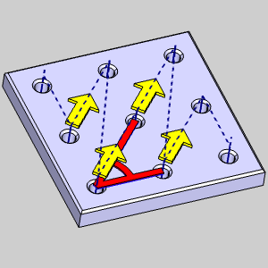
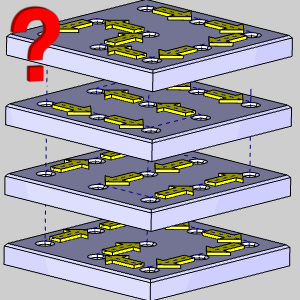
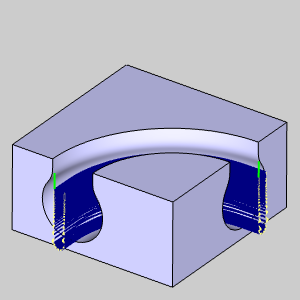
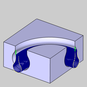
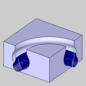
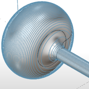
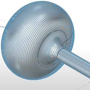
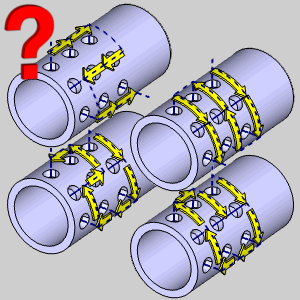
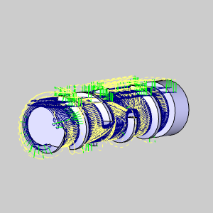
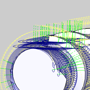
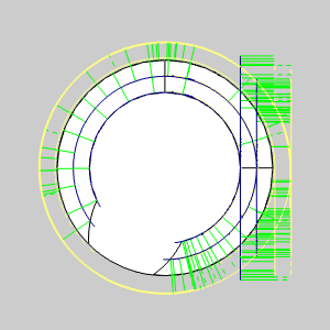
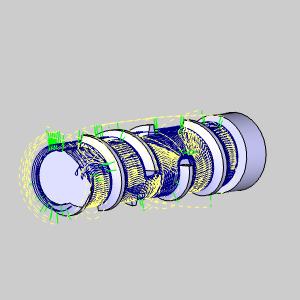
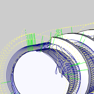
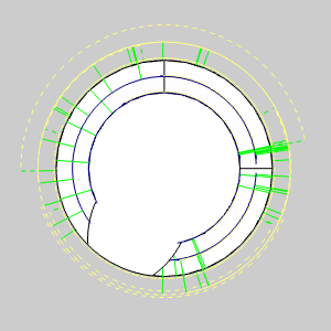
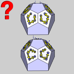
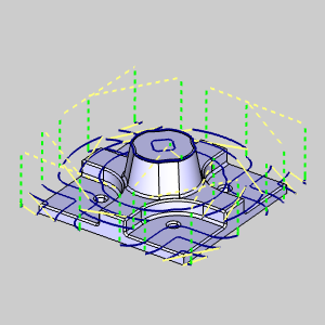
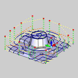
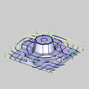
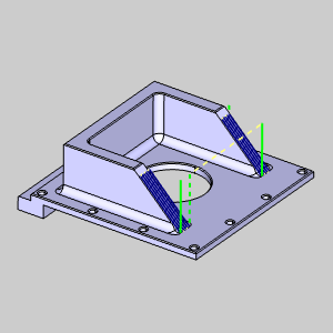
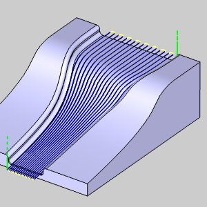
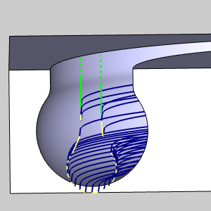
The new algorithm in the Multiaxis Roughing now supports rotational, or so called periodic pocket geometries. This was considered a major limitation to multiaxis machining even though the initial design was never supposed to support it. The tool does not continuously follow the pocket, but an overlap is guaranteed when the pattern returns on the surface edge seam. As seen in the image below, the new algorithm helps to ensure that all areas are handled with smooth multiaxis movements.
Old |
Old |
Old |
|
|
|
|
|
|
New |
New |
New |
|
|
|
This feature is for shifting the tool contact point as it moves along the contour. This can be used for a polishing process, where in the beginning of the machining process the tool sits on the front, and at the ends it runs on the heel.
On |
Off |
|
|
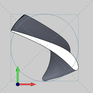
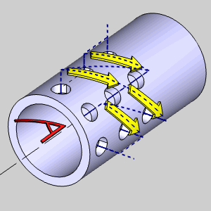
This new feature gives an incredible amount of control over the range of tilt during machining. While there are many options when it comes to setting the tilt of the tool, there has never been an option quite like this one. Just define the start angle and the end angle, and the tool gradually changes the tilt angle between those angles. This is extremely helpful in cases similar to a turbine blade finishing toolpath, and can help to ensure that the tool stays clear of obstacles like the blade root.
This feature enables two contours to be linked with a new blend spline and is available for Gaps along cut, and Links between Slices and Passes. This option enables a smooth transition between contours and In the event of a detected collision, the blend spline is extended to ensure the main shape is not disturbed and to guarantee a smooth transition.
The new Automatic Arc lead option is a great way to ensure nice, clean leads. The automatic arc consists of two splines. The first spline leaves the surface tangentially in the surface normal direction, similar to a tangential arc. The second spline connects tangentially into the plunge or retract motion, using the tool axis tilting orientation. This lead option even works in combination with collision checking.
When using the Position Line lead option, the start/end position of a cut is defined by a line. The line defines the direction of the tool axis as well as the height of the tool. Because this line is absolute, all following retractions will go to same position and height. A new option has been added to this lead called Automatic start height. Using this option means the height along the line is not absolute, but is automatically adjusted to the cut position.
|
To give you the control you need, the sorting algorithm for multiple cuts has been extended. For best material removal performance, the first cut can now start from the bottom. You're welcome.
Taking us another step closer to one-click machining, is the new Automatic Clearance Area. While, most will want to have control over the exact clearance area types, and distances being used, with this new feature, the system automatically determines the clearance area type, position and dimension. It tries to maintain the most suitable setting for each pattern. It doesn't get any easier than that.
New Multiaxis Posting options are available when using Select Between The Two Solutions. When moving the material and tool into position, there are instances where two solutions which achieve the same result, and in the past, you could choose between them with the options First Solution and Other Solution. The only problem with this, was that it could be frustrating in cases where you have a particular outcome in mind. In those instances, if the first solution wasn't what you were looking for, you would need to go back and choose Other Solution. Now, other options exist that give predictable results: Solution closest to 0 and Solution not closest to 0. With these options, the sum of the 2 angles has been found for each solution. This way, when you select Solution closest to 0, you know which result you are choosing.
|
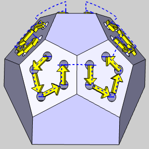
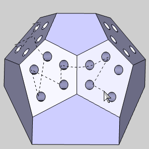
BobCAD-CAM now offers new and improved sequencing options in order to offer lower cycle times. Whether you are creating a Standard Drill, Multiaxis Drill, or even a Cross Drilling feature you will find new, highly effective ways to maximize the efficiency of the sequence. Our Mulitaxis Drilling offers Closest, Pick Order, and an Optimized sequence. The Closest sequence automatically moves to the next closest hole, Pick Order allows you to select the geometry in the order you would like it machined, and Optimized will test its own algorithm against the result of the Closest sequence to give you the shortest possible toolpath. We even go a step further in offering a 'Reverse Each Operation' option to save even more moves. With Reverse Each Operation, drilling features that contain multiple operations, can have subsequent operations track back along the path of the first operation to keep the tool from having to move all the way back to the beginning to start the path again.
Multiaxis Drilling |
||
Closest |
Pick Order |
Optimized |
|
|
|
|
|
|
Cutting air is always something to avoid in machining. In the past, there were ways to work around the issue. But when we offered our customers the ability to assign operational stock to milling operations, to focus cuts on the stock itself, our users were elated! Now, BobCAD-CAM offers the same functionality in lathe, and even goes a step further by tracking the effects of each operation without the need to save the stock as an .STL, to then assign to particular operations. In this release, each operation automatically updates the operation stock of the following feature! This new functionality, used hand-in-hand with our Trim to Stock feature helps eliminate pesky air cuts.
Tracked Stock Before Operation |
Operation |
Tracked Stock After Operation |
|
|
|
In the past, a features toolpath was all the same height, unless it was an offset of the selected geometry. Offsetting toolpath was the best way to handle cast stock, but in that, and certain other situations, you could still be left with small areas of toolpath cutting air. Now in BobCAD-CAM V30, we offer a way to trim away unwanted portions of toolpath with the Trim to Stock option. With the simple selection of a check box, BobCAD-CAM will now be able to trim away all air cuts and focus only on stock.
Tracked Stock Before Operation |
Default Operation |
Operation with Trim to Stock |
|
|
|
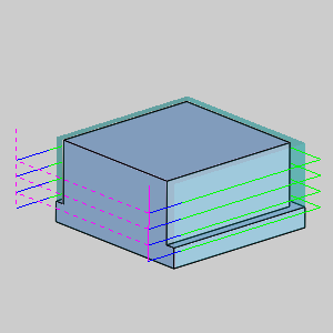
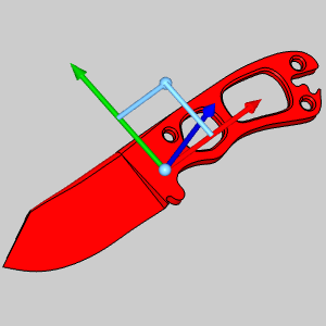
This new option is the easiest way yet to get familiar with a machine and its axes. In the past, when getting familiar with a machine, the best way to test machine components in the graphics area, was to go into the axis control pane, and start clicking on the sliders for each axis to move it up and down. This would, in turn, move the associated machine component in the graphics area. Now, you can simply go into the machine pane and click on an axis. The associated machine component will then highlight in the graphics area, and will even display an arrow showing positive direction and rotation when applicable. This helps end guessing work and gives you a ton of data at a simple glance.
In previous versions, you could click on an item in the Machine tree to have the object highlight in the graphics area. This could be useful if you wanted to know what axis a particular object in the graphics area was linked to. The drawback, however, was you would need to go through the machine tree clicking items until the object of interest highlighted in the graphics area. Now you can hold Ctrl and double right-click directly on an object in the graphics area and the associated item will highlight in the machine tree.
The simulation should be as informative as possible at simple glance. In order to assist in this, the objects in the viewing area are color coded for each Collision Checking group and grey for non-selected objects. Just click on the Collision Check group in the machine list and the objects in the graphics area will highlight to show you what is being checked against what.
The Move List pane now has the ability to adjust the order of the columns, resize the columns, and even has a handy new addition called the Field Chooser. Right-click anywhere in the pane and select Field Chooser and you can drag and drop additional columns to and from the field chooser with ease! Now you have control over the look and content of the Move List.
The Axis Control pane has been updated to give you the ability to set the axis to a particular value directly in the pane. In the past, if you wanted to set an axis to a particular location, you had to right click on the slider to launch the Set Axis Values dialog box. The axes could then be adjusted to a particular location, but that value had to be entered in specifically, and the result could not be seen until you exited the dialog. Now, these adjustments can be made without launching a separate dialog, and a stepper has been added for those instances when the exact location is not known. Simply use the slider to get close and the stepper to hone in on the exact figure.
All pop-up notifications have been improved and now have different options for disabling their display during simulation runs. To give you as much control as possible, the pop-ups can be disabled according to different groups and criteria.
During mouse rotation in Machine Simulation, a dot is displayed to show the selected rotation center point.
While there have always been options for chip removal in the simulation, this has always been something that had to be done by the user after the simulation had ended. Now, you can set chips to be automatically removed as they are created!
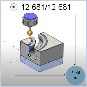
The ruler shown in the bottom corner of the simulation now has a vertical aspect to show height. In the past, the on screen ruler only displayed the width. This has been updated to give you a better understanding of size without the need to enter the measurement functions.

 Sharp Corner
 Sharp Corner