
In this Topic Show
This tutorial explains how to create a Multiaxis feature with the Roughing toolpath. Multiaxis Roughing always uses the surface normal direction of the part to define the tool axis orientation. The example explains proper geometry selection based on the roughing strategy used.
The BobCAD part file for this tutorial is available for download at: http://bobcad.com/helpfiles. If you are connected to the Internet, you can click the link provided to download and save the Multiaxis Roughing Example 1 BBCD.zip file. After extracting the zip file, you can open the file to follow along with this example. In the example file provided, the stock and Machine Setup are already defined for the part. The part is simulated using the BC Table-Table machine.
1 In
the Data-CAM Tree Manager, click
the  CAM Tree tab.
2 Right-click
 Machine Setup
and click Mill Multiaxis.
Machine Setup
and click Mill Multiaxis.
3 In the Multiaxis Wizard, click Multiaxis Roughing.
4 Click Next>> to go to the Posting settings.
1 The Work Offset # is automatically set to the value defined in the Machine Setup.
You can change the value here to update the Work Offset # for the feature.
2 Click Next>> to go to the Multiaxis Posting settings.
1 Notice, at the top of the dialog box, that the Use Machine Settings check box is selected.
This means that the Multiaxis Posting parameters for the feature use the same parameters as the machine that is selected in Current Settings.
You can clear the Use Machine Settings check box to define the Multiaxis Posting parameters of the feature separately from the current machine settings.
For this example, no changes are needed.
2 Click Next>> to go to the Tool settings.
1 Click Tool Crib.
2 Under Tool Category, click Endmill Rough, and click Add from Tool Library.
3 In the Select Tool dialog box, click the column label Diameter to sort the list.
4 Click anywhere in the row of the 3/4 Flat Endmill - Long tool, and click OK.
Click OK in the Tool Crib.
5 Click Assign Tool Holder.
In the Milling Tool Holder Library, click to select 0.75 inch I.D. Arbor CAT 40.
Click OK.
6 Click Next>> to go to the Parameters.
1 Click the Part Definition tab.
2 Under
Part Definition, next to Floor Surfaces,
click  .
.
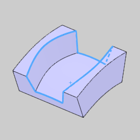
Select the floor surface as shown next.
This defines the area to which the toolpath is applied.
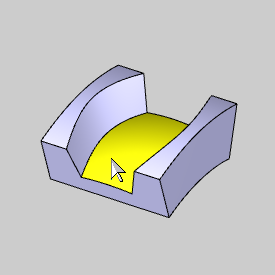
To confirm the selection, click  .
.
3 In
the Part Definition group, next
to Wall Surfaces, click .
Click and drag a window to select the entire part as shown next.
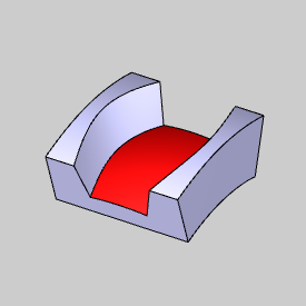
Click the floor surface to remove it from the selection.


Click .
For this example, we removed the floor surface from the Wall Surfaces selection, but this isn't required. We do this so that we can define separate Stock to Leave values for the wall and floor surfaces.
4 Next to Floor Surfaces, in the Stock to Leave box, type 0.030.
Next to Wall Surfaces, in the Stock to Leave box, type 0.015.
This leaves material remaining for a finishing operation on the wall and floor surfaces.
IMPORTANT: When selecting the Wall Surfaces, you can select the entire part, but do not include the ceiling surface.
1 Click the Surface Paths tab.
2 To create a toolpath of parallel cuts that is offset from the floor surface: under Pattern, next to Strategy, select Offset From Floor.
For this example, the default Type, Offset, is used. If you want to make the Multiaxis Roughing operation a high-speed machining operation, change the type to Adaptive. The Adaptive pattern automatically creates the high-speed machining without any other settings required. Be aware that some available feature parameters change slightly depending on the selected pattern Type.
3 To define the depth of cut, in the Constant Depth Step box, type 0.500.
This value is the maximum depth of cut and the system automatically creates the number of passes necessary to machine the part.
4 In the Sorting group, set the Cutting Method, to Zigzag.
5 In the Stepover group, set the Maximum Stepover amount to 0.375.
6 At the top of the dialog box, click Roughing.
Confirm that the  Stock Definition check box is selected.
(If the check box is cleared, no toolpath is created.)
Stock Definition check box is selected.
(If the check box is cleared, no toolpath is created.)
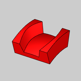
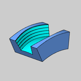
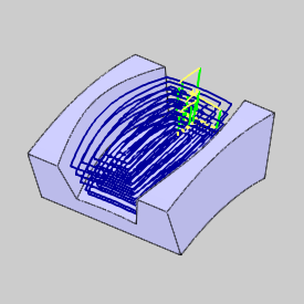
7 At the bottom of the Multiaxis Wizard, click Compute.
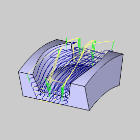
The following image shows the part after simulation.
(To simulate the toolpath, in the Modules
menu, click  Simulation.)

When using the strategy Offset From Floor, you do not need to define a ceiling surface. For the other two strategies, Offset From Ceiling and Morph Between Ceiling and Floor, you must define a Ceiling Surface. The ceiling surface must span the entire area of the part, and is often the top surface of the stock geometry.
1 The Stock geometry must be shown before selecting the ceiling surface.
In the Layers tab, right-click Stock and click Show.
(To hide the part geometry, right-click Part Model, and click Hide. This step is not required, but makes it easier to select the proper geometry.)
2 To define a ceiling surface, in the CAM Tree, right-click Ceiling Surface, and click Re/Select. (You may need to expand the Geometry folder of the Multiaxis feature.)
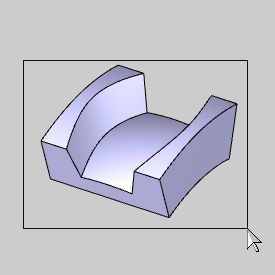
Select the top surface as shown next.
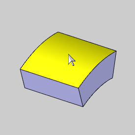
Click .
3 To
edit the feature, in the
CAM Tree, right-click  Feature
Multiaxis, and click Edit.
Feature
Multiaxis, and click Edit.
4 Click Parameters.
5 In the Surface Paths tab, in the Pattern group, select the Strategy as follows:
If you select the Strategy Offset From Ceiling, the toolpath cuts are created parallel to the ceiling surface.
If you select the Strategy Morph Between Ceiling and Floor, the feature creates an offset from the ceiling and an offset from the floor and blends (morphs) the two paths together to create the toolpath.
In the Surface Paths tab of the Multiaxis wizard, the 3D Containment allows you to limit the Multiaxis Roughing operation using a 3-dimensional containment curve. The following is a quick example usage.
The part in this example is an open pocket, which allows the toolpath to continue past the bounds of the part. Let's imagine that this is not the desired result, but you don't want to create new geometry to create a closed pocket. You can select the edges directly from the model to contain the toolpath within the bounds of the part.
For visual reference, the following image shows the original toolpath created in this example.
1 In the Area group of the Surface Paths tab, select the 3D Containment check box.
2 Click 3D Containment and select the 3D containment curves from wireframe geometry or directly from the model edges.
Click .
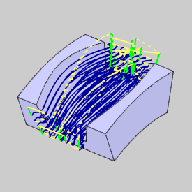
3 Click Compute.
The toolpath is now contained within the selected 3D boundary.
This concludes the tutorial.