 CAM Tree,
right-click Machine Setup and
click Mill Drill Hole.
CAM Tree,
right-click Machine Setup and
click Mill Drill Hole.In this Topic Show
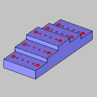
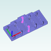
This topic provides an example of how to create standard hole drilling features for milling jobs in BobCAD-CAM. Standard Mill Hole features are used when drilling holes that are parallel to the Z-axis of the machine. This is the most commonly utilized drilling type in BobCAD-CAM.
This tutorial highlights the following functionality of the BobCAD-CAM software:
The BobCAD part file for this tutorial is available for download at: http://bobcad.com/helpfiles. If you are connected to the Internet, you can click the link provided to download and save the Mill Standard Drilling Example 1 BBCD.zip file. After extracting the zip file, you can open the file to follow along with this example. In the example file provided, the job, stock, and machine setup are already defined.
1 In
the CAM Tree,
right-click Machine Setup and
click Mill Drill Hole.
2 In the Mill Hole Wizard, click Select Geometry.
The Hole Geometry Selection Manager displays.
3 Confirm that the default drilling type, Standard Drill, is selected.
For this example, you can select the cylindrical surface of each hole directly from the model, but to make selection easier, a separate CAD layer contains a copy of only these surfaces. (Note that the Point and Arc Usage options do not apply when selecting cylindrical surfaces.)
IMPORTANT: We are selecting cylindrical surfaces because this allows the software to automatically set our diameter, top of feature, and feature depth. To learn about selecting other geometry types, view the Point and Arc Usage Example.
4 In the Edit menu, point to Select Entities, and click Pick by Layer.
5 In the Select Layer dialog box, click Holes.
Click OK.
6 Click OK in the Selection Manager.
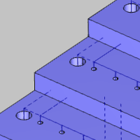
Geometry selection is finished. Notice the hole list displays each diameter hole and its parameters. The software automatically creates a separate Mill Hole feature for each hole diameter. The Depth value for both of our hole sizes displays as Multiple. This is due to the multiple depths that are achieved in a single feature using hole groups. The hole depths can be modified in the wizard later, as needed.
7 Click Next>> to begin defining the parameters for the first hole diameter (feature).
The Hole Groups table is an important part of the Feature page in the Mill Hole Wizard. Each hole group represents a different hole depth, and the Hole Groups table allows you to preview, break, regroup, rename, and set the parameters for all hole groups in the feature. For more information, view the Hole Groups topic.
1 For now, we are using the default Material Approach settings.
The Diameter is already properly set from the selected geometry.
The Parameters are also already properly set for this example.
2 Under Hole Groups, click anywhere in the row of Group 1 to select it.
Because the group is now selected, the hole groups preview displays inside the dialog box.
To change the viewing orientation of the preview, drag the left or middle mouse button to rotate. To pan the preview, press and hold the Ctrl key, and drag the middle mouse button. To zoom in or out, roll the middle mouse button forward or backward.
3 In the Hole Groups table, click the name Group 1, and type Low.
This hole group is on the lowest level of the part, and our custom naming is more descriptive than Group 1. Renaming hole groups is a great way to stay organized when there are many hole groups.
TIP: To edit a hole group name, top of feature, or feature depth, click the value (or name) directly in the Hole Groups table. Type the new value or name to update it. After editing any value, you can press Tab to move to the next parameter in the list, or press Enter to finish.
4 Under Hole Groups, click the name Group 2.
5 Type Mid to rename Group 2.
6 Click the name Group 3, and type High.
We don't make any other changes to the hole groups at this time. Remember that we selected cylindrical surfaces so the parameters for the hole groups are automatically set.
7 Click Next>>.
1 Under Template, click the Hole machining strategy template.
This assigns one center drill operation and one drill operation to the Current Operations list.
2 On the lower left, click Apply to All Features.
The software automatically creates one feature for each hole diameter as seen in the tree on the left. The second feature now uses the same Machining Strategy as the first.
3 Click Next>> twice to go to the center drill tool data. (No changes are needed for the posting settings.)
1 Notice the System Tool check box is selected. For this example, we use the automatically selected system tool information, but be sure to update the tool data, machining data, and feeds and speeds as needed when creating your own programs.
2 Click Next>>.
Again, we use the default operation parameters, but notice there are no hole groups listed. For center drill and chamfer operations, the parameters defined here are shared across all hole groups. All other operation types allow you to define the parameters for each hole group separately.
3 Click Next>>.
We use System Tool information again for the drill operation, because the software automatically loads a tool with the correct diameter from the Tool Library. All of the parameters stored with the tool are automatically set in the wizard.
4 Click Next>>.
5 Notice the Hole Groups list. Click Low to select it.
Under Cycle Type, click Peck.
6 Click the group name Mid, and then select Peck.
Set the High group to Peck using the same process.
IMPORTANT: Be sure to select a hole group before changing any operation parameters, and make sure to set the parameters as needed for all hole groups.
7 Click Next>>.
1 In the Hole Groups table, repeat the process of selecting the group to view the preview, and then rename each group to Low, Mid, and High based on its level on the model.
Again, the hole groups parameters are automatically set because we selected cylindrical surfaces.
2 Click Next>>, and notice that the Hole operation template is selected from using Apply to All Features earlier.
3 In the tree on the left, click the last Parameters item.
4 Repeat the process as explained earlier to set all hole groups to the Peck cycle type.
5 On the lower-right, click Compute.
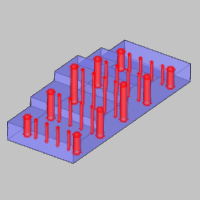
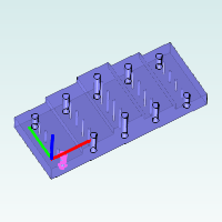
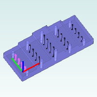
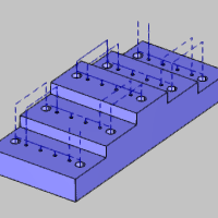
The resulting toolpath is shown next.
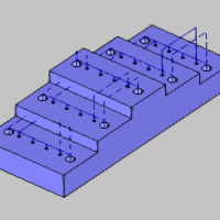
After viewing the toolpath, we see one issue. The rapid plane, applied within hole groups, is going through the steps of the model because the holes on opposite sides of the part are in the same group. The rapid movement between hole groups is determined by the group retracts as seen in the link moves that retract up above the part. Next we modify our hole groups to alleviate the issue.
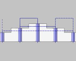
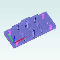
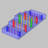
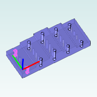
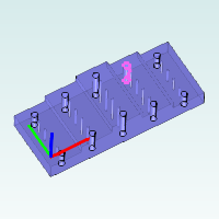
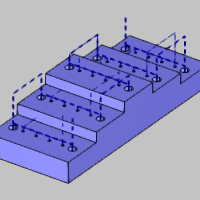
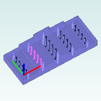
For reference, the following image shows the current hole groups using one color for each group. Remember that each hole diameter is a single feature and we are working with two features (both are shown in the image).
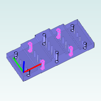
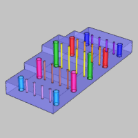
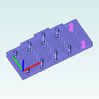
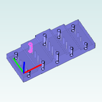
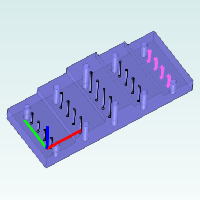
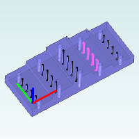
After breaking and regrouping holes in the following steps, the hole groups are as follows (one color for each hole group). This final grouping allows us to optimize the toolpath for both features.
1 In the CAM Tree, right-click the first feature name, Standard Feature Mill Hole - 0.3750, and click Edit.
Click the Group Retracts button under Material Approach.
The group retracts handle the rapid movement between hole groups, and they are currently set to a plane in Z with a height of 0.6250. This distance is in reference to the machine setup (machining origin) location, which is at the top of the part.
Close the Group Retracts dialog box.
Next we modify our hole groups so the group retracts are used when moving from one step (level) of the model to the next.
2 Under Hole Groups, click anywhere in the row of the Low group to select the group and display the preview.
3 With the Low group selected, click Break Hole Group.
The group is separated into four single-hole groups (Low.1 through Low.4).
4 Click anywhere in the row of group Low.1 to select it.
Press and hold the Ctrl key, and click Low.2 to add it to the current selection.
We can see that Low.2 is on the opposite side of the part so we don't want to regroup these holes.
TIP: You multi-select items in the Hole Groups list using the Shift and/or Ctrl keys. Hold Ctrl and click a group to add it to or remove it from the current selection. Hold Shift and click a group to select all groups between the first and second selections.
Hold the Ctrl key and select group Low.2 to remove it from the selection. (Click the row of Low.2 in the Number column.)
Press Ctrl and click Low.4 to add it to the selection.
We can see that Low.1 and Low.4 are on the same side of the part, so these are the two holes we want to regroup.
5 With both Low.1 and Low.4 selected, click Regroup Holes.
Click the new group Low.1 to confirm the new grouping.
6 There are only two holes left on the lower level, so click Low.2, then hold Ctrl and click Low.3.
Click Regroup Holes to create a new Low.2 group.
7 Repeat this process of breaking and regrouping holes for the middle level (group Mid) so that each group only contains the holes that are on the same side of the part.
There is no need to break the High hole group.
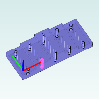
Breaking group Mid results in the following groups.
Mid.1 |
Mid.2 |
 |
 |
Mid.3 |
Mid.4 |
 |
 |
Groups Mid.1 and Mid.4 are regrouped to create a new group, Mid.1.
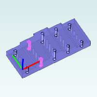
Groups Mid.2 and Mid.3 are regrouped to create a new group, Mid.2.
To update the changes for this feature, click Compute.
Now we break and regroup the holes for the second feature. Again, the process here is to use the Ctrl key to add and remove selections while viewing the hole groups preview, and then regrouping the holes as needed. In this section we use the Shift modifier to select multiple list items.
1 Right-click the second feature name, Standard Feature Mill Hole - 0.1250, and click Edit.
2 Under Hole Groups, click anywhere in the row of group Low to select it.
Press and hold Ctrl, and select group Mid.
With Low and Mid selected, click Break Hole Group.
3 Select group Low.1 and observe the hole groups preview.
Hold Ctrl and select Low.2.
Group Low.2 is on the opposite side from Low.1 and we want to regroup holes that are on the same side of the part.
Hold Ctrl and click Low.2 to remove it from the selection.
Group Low.3 is also on the opposite side of the part.
Hold Ctrl and click Low.4 to add it to the selection.
We hold Ctrl and select all the low level holes that are on the same side of the part: Low.5 and Low.8.
4 With Low.1, Low.4, Low.5, and Low.8 selected, click Regroup Holes.
Click the new Low.1 group to display the preview.
5 Click group Low.2.
Press and hold the Shift key, and click group Low.7.
Notice that all groups from Low.2 through Low.7 are selected.
Click Regroup Holes.
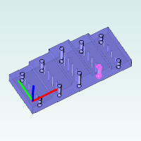
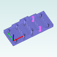
6 Repeat this process to regroup the mid-level holes using the same process. (Group Mid is regrouped into Mid.1 and Mid.2 as shown next.)
7 Click Compute to update the toolpath.
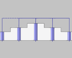
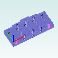
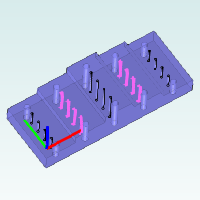
The result of breaking the hole groups is an efficient toolpath for our example part that uses a minimal rapid plane within groups and only retracts above the part to move from one group to the next (group retracts).
This concludes the tutorial.