In this Topic Show
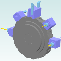
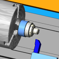
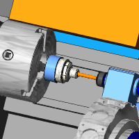
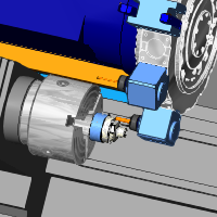
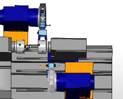
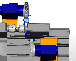
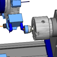
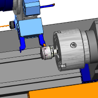
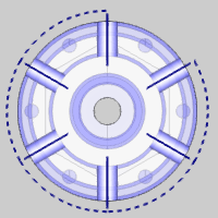
This tutorial walks you through creating a Mill Turn job to completely machine an example part on the BC 2T 2S mill-turn machine as shown in the Mill Turn Tutorials topic. This is a two turret, two spindle configuration with live-tooling and Y-axis machining capabilities on the upper turret. In addition to understanding the machine for which we are programming, it is also important to know the naming convention used for the submachines (work zones) as follows.
This tutorial uses the BC 2T 2S Mill Turn machine.
The submachine naming used for the BC 2T 2S is as follows.
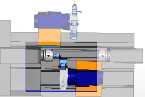
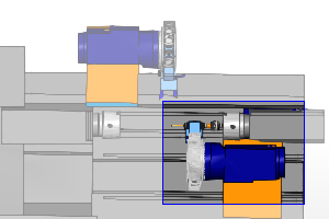
UT_MS = Upper Turret, Main Spindle |
UT_SS = Upper Turret, Sub Spindle |
 |
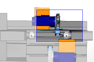 |
LT_MS = Lower Turret, Main Spindle |
LT_MS = Lower Turret, Sub Spindle |
 |
 |
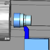
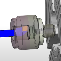
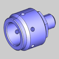
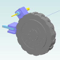
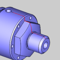
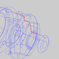
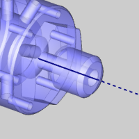
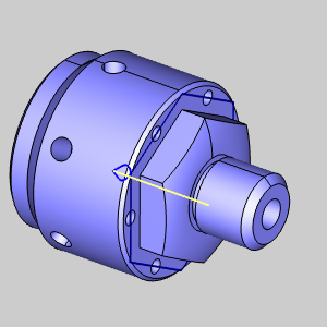
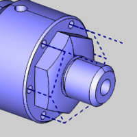
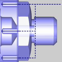
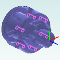
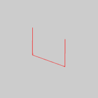
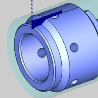
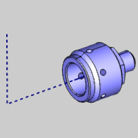
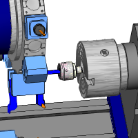
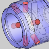
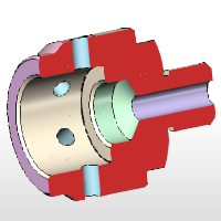
The following images show our example part. For this tutorial, we machine the part using stock that is already cut to length. For this reason, we create our features as though the model is split into two halves: front and back. This allows us to machine the front half of the part on the main spindle before transferring the part to the sub spindle and machining the back half. This is important to understand as this determines how we create some of our features.
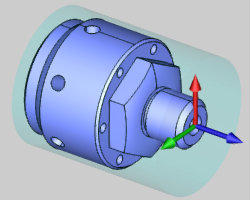
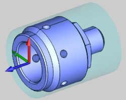
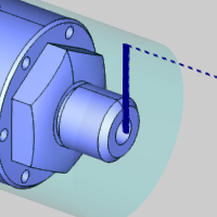
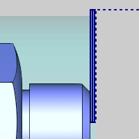
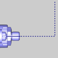
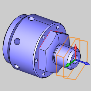
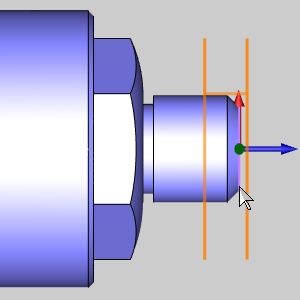
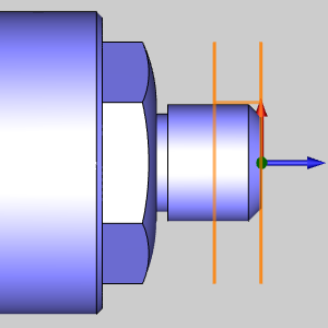
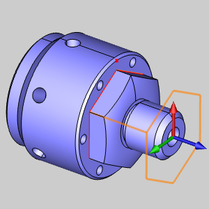
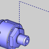
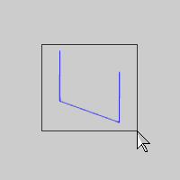
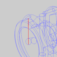
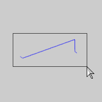
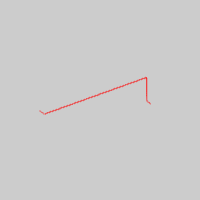
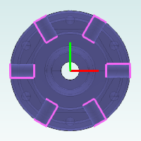
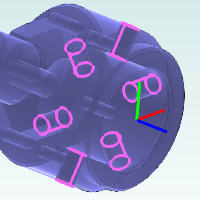
For this tutorial, all features are created using one of two machine setups: one for the front side and one for the back side of the part. The following images show the location and orientation of the machining origin (work offset) for each setup.
Machine Setup 1 |
Machine Setup 2 |
 |
 |
The Mill Turn job, stock, and machine setups are already defined in the example file provided for this tutorial. If you would like to learn more, view the Mill Turn Job Setup Example.
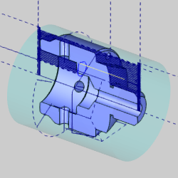
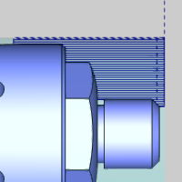
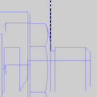
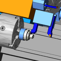
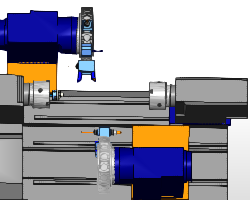
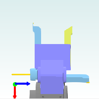
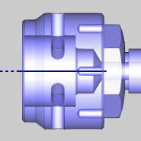
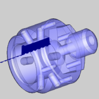
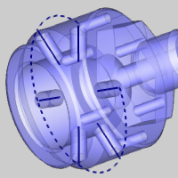
Next is a sectional view of the model that is used to show all of the toolpath created to machine the part in this tutorial.
The BobCAD part file for this tutorial is available for download at: http://bobcad.com/helpfiles. If you are connected to the Internet, you can click the link provided to download and save the Mill Turn Example 1 BBCD.zip file. After extracting the zip file, you can open the BobCAD file to follow along with this example. In the example file provided, the job, stock, and two machine setups are already defined.
This tutorial highlights the following features of the BobCAD-CAM software:
For this example, we load the Tool Crib with all tools that we want to use for the job. This way, we only open the Tool Crib to confirm the proper tool selection or to change the default assignment, for example, when selecting a finish tool for a rough operation or vice versa.
TIP: The ability to save and load the Tool Crib is an invaluable tool that can save a significant amount of time when creating Mill Turn jobs in BobCAD-CAM. If you have resident tools and/or adapters, or tools and adapters that are generally always mounted to the turret of the physical machine, then you can load and mount these tools in the Tool Crib once, and then save the information to a file to use as a template. This way you can just load the file, and you only need to add additional tools as needed per job. You can even save a Tool Crib for each machine or each common configuration that you use.
1 In the CAM Tree Manager, right-click Mill Turn Tools, and click Tool Crib.
The Mill Turn Tool Crib displays.
2 Click the Load button.
The Open dialog box displays for you to select a previously saved tool crib file.
3 Navigate to the Mill Turn Example 1 folder, and click to select the Mill Turn Example 1.mttcribs file, and click Open.
Notice that the upper turret and lower turret devices now contain all the adapters and tools needed to complete the entire job. The mounting parameters are already set as needed to match how we are mounting our tools on the physical machine.
4 Click OK to save the tool information to the job.
Watch Video - How to Load a Tool Crib from a File
The first three features that we create use the LT_MS (lower turret, main spindle) submachine or work zone. Instead of changing the submachine in the Posting page of each feature, we change the submachine in the CAM Tree to determine the default submachine for creating new features.
1 Under Machine Setup - 1, right-click the current submachine name (UT_MS), and click Edit.
2 Under Submachine Name, click the down arrow, and select LT_MS.
3 Click OK to update the default submachine.
All machining features created under Machine Setup - 1 are automatically set to use this submachine. The submachine can always be changed in the Posting page of the wizard.
It is important to think about the machine setup (machining origin) when creating machining features for Mill Turn jobs. All of the features that we create to machine the front half of the part are created under Machine Setup 1. The machining origin for this machine setup is at the front face of the part, not the stock, (we are facing to zero).
To learn how to define the machine setups for this example file, view the Mill Turn Job Setup Example.
1 Right-click Machine Setup - 1, point to Turn Features, and click Lathe Turning.
2 Click the Select Geometry button to hide the wizard and show the graphics area.
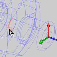
3 On the Layers tab of Layer-UCS-Post Manager, right-click the layer name Front Face, and click Show.
4 Click to select the line.
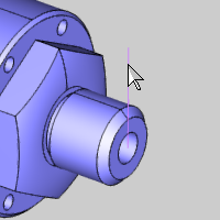
5 Click
 to confirm the selection.
6 Click Next>> to go to the Feature settings.
1 The Feature page of the wizard displays the stock settings that were automatically detected and set based on our stock geometry and work offset (machining origin) location from the (predefined) Stock Wizard and Machine Setup. The software uses these values to determine the location of the first cut, and because they are automatically set, we do not need to modify these values for this feature.
2 Click Next>> to go to the Machining Strategy.
The default template, Face Rough, doesn't need changed, but we remove our finish operation. We simply use the roughing operation to cut the face to its final depth.
3 Under
Current Operations, click to select
Face Basic Finish, and click  (Delete Operation).
4 Click Next>> to go to the Posting settings.
5 Under Posting Parameters, click the down arrow and select Canned Cycles.
TIP: Notice the Submachine group in the Posting page of the wizard. You can always change the submachine for the feature from this location, in the event it is different from the default submachine selected in the CAM Tree.
6 Click Next>> to go to the Tool settings.
NOTE: In this example, we loaded the Tool Crib before creating our job. This was done to show how much faster this method is, but you do not have to work this way. You can always load and mount tools in the Tool Crib as you create machining features. BobCAD-CAM allows you to work to your preferences.
Next we open the Tool Crib simply to verify the correct tool assignment (this step is not actually required, but is done for example purposes). We can determine which tool is selected by viewing the Tool Label, but it can also be helpful to open the Tool Crib to view and confirm the mounting orientation of the tool for each operation.
1 Click the Tool Crib button.
The Mill Turn Tool Crib displays.
Notice in the device tree on the left that the 80 Deg. 1/64 Rough Turning tool is selected under lower turret Station #17 (the first station of the lower turret).
Note that only the lower turret displays in the device tree, because our feature is set to the LT_MS (lower turret, main spindle) submachine.
We can also see that the tool is properly mounted and oriented to face the front side of the part.
2 With the 80 Deg. 1/64 Rough Turning tool still selected, click OK.
IMPORTANT: When opening the Tool Crib from within a CAM Wizard, the tool that is selected when you click OK is assigned to the operation. Always be sure that the correct tool is selected before clicking OK in the Tool Crib. (The tool can be selected in the Device Tree or the Tool list.)
3 Click Next>> to go to the Parameters.
4 Under Parameters, make the following changes:
Depth of Cut = 0.030
Z Allowance = 0.00
X Allowance = 0.00
Notice that we set the allowance values to zero so that no extra stock remains after the rough operation (we are not using a finish operation).
5 In the tree on the left, click Leads. (You can navigate through the wizard using the tree or the Next and Previous buttons.)
Change the Lead-in X value to 0.100.
Change the Lead-out Z value to 0.100.
6 At the bottom of the wizard, click Compute to calculate the toolpath.
Before creating another feature, we simulate to confirm the toolpath is correct. The following steps provide an example of some settings that you may want to use during simulation. You can use some or all of these settings when simulating other features later in this tutorial.
1 To open simulation, right-click Mill Turn Job, and click Simulation.
2 The following provides some suggested simulation settings to get started.
 Machine
Housing button to show the entire machine. For the BC 2T
2S machine, the machine base is assigned as part of the machine
housing. (
Machine
Housing button to show the entire machine. For the BC 2T
2S machine, the machine base is assigned as part of the machine
housing. ( Machine Focus should also be
selected in the Simulation
group of the Simulation
tab.)
Machine Focus should also be
selected in the Simulation
group of the Simulation
tab.) Toolpath
button to hide the toolpath from view.
Toolpath
button to hide the toolpath from view. Workpiece and
  Stock
buttons are set to show the workpiece and stock.
Stock
buttons are set to show the workpiece and stock. Simulation
Run Speed slider
to adjust the playback speed of simulation as needed while simulating.
Simulation
Run Speed slider
to adjust the playback speed of simulation as needed while simulating.
3 Click
the  Run button
to play the simulation.
Run button
to play the simulation.
The simulation confirms that the desired toolpath is achieved.
4 To
close the simulation, click the  Exit Simulation button.
For more help with our extremely powerful simulation, view Getting Started with Simulation.
Now that our feature is finished, we can hide the facing geometry and hide the toolpath from view with the following steps.
1 In the Layers Manager, right-click Front Face, and click Hide.
2 In the CAM Tree, right-click Feature Lathe Turning, and click Blank/Unblank Toolpath.
3 Click the small minus sign next to the feature to collapse it.
4 In the File menu, click Save.
Always be sure to save your work, and save it often.
Watch Video - How to Create a Turning Feature - Facing
Now we create a turning feature to rough and finish the outside diameter (OD) of the part. Note that we are splitting the front and back half of the part, so the front half is machined on the main spindle and the back half is machined on the sub spindle.
1 Right-click Machine Setup - 1, point to Turn Features, and click Lathe Turning.
2 Click the Select Geometry button to hide the wizard and show the graphics area.
3 On the Layers tab of Layer-UCS-Post Manager, right-click the layer name Front Turn, and click Show.
In the Edit menu, point to Select Entities, and click Pick By Layer.
In the Select Layer dialog box, click Front Turn, and click OK.
4 To
confirm the selection, click .
5 Click Next>> twice to go to the Machining Strategy.
1 Under Template, click Turn Rough.
The Current Operations list now displays one Turn Rough operation and one Turn Basic Finish operation.
2 Click Next>> to go to the Posting settings.
3 Under Posting Parameters, click the down arrow and select Canned Cycles.
4 Click Next>> to go to the Tool settings.
1 We don't need to open the Tool Crib this time, as the software already assigned the appropriate tool (80 Deg. 1/64 Rough).
2 Click Next>> to go to the Parameters.
3 Under Parameters, make the following changes:
Depth of Cut = 0.040
Z Allowance = 0.0030
4 Click Next>> to go to the Rapids settings.
Under Type, click the down arrow and select Rapid On Exit To Cycle Start X-Z.
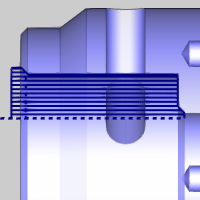
This setting reduces the amount of tool movement between operations, as it returns to the cycle start instead of the home position defined for the tool. Note that this option moves in X first and then in Z as shown in the wizard image.
5 Click Next>> to go to the Leads settings and make the following changes:
Lead-in Z = 0.100
Lead-out X = 0.100
6 On the lower-left, click Apply to All Operations so that the finish operation uses the same leads settings.
In this part of the example, we show an important tip for tool assignment in Mill Tun jobs. We are using the same turning tool to rough and finish the part as this reduces the number of tools that we need to mount on the machine. Next, we change the tool assignment for the finish operation to use the rough tool.
1 Under Turn Basic Finish, click Finish.
2 Click the Tool Crib button.
NOTE: At the bottom of the device tree, notice there is a tool under the Loose tools category. This is the tool that the system automatically assigned because our tool crib (lower turret) does not contain any lathe finish tools. Next, we change this operation to use a tool from the rough category.
3 On the lower-left under Tool Category, click Lathe Rough.
TIP: You can select a category under Tool Category to filter the tools list to show only tools from that category, which makes it easier to locate the appropriate tool. This is extremely helpful when there are a lot of tools in the job.
4 Click to select the only tool in the tools list, 80 Deg. 1/64 Rough Turning.
Notice that the tool also highlights in the device tree to show its location.
Click OK.
5 You can go to the Leads settings and confirm that they are already set from using Apply to All Operations earlier (this step is optional).
6 At the bottom of the wizard, click Compute to calculate the toolpath.
Next we simulate the program to view the second feature operations.
1 In the Modules menu, click Simulation. (This is another way to launch the simulation.)
2 In the information and analysis tabs on the right, click the Move List tab to show it.
3 At the top of the list, click Op. 2: Turn Rough-80 Deg 1/64 Rough Turning to advance the simulation to the start of the rough turning operation.
TIP: In the Move List tab of the simulation window, you can click the operations in the list to go directly to the start of the selected operation.
4 Click
the Run button
to play the simulation.
Again, we are happy with the result, so no changes are needed for this feature.
5 To
close the simulation, click the
Exit Simulation button.
As shown earlier, we can hide the turning geometry and hide the toolpath from view with the following steps.
1 In the Layers Manager, right-click Front Turn, and click Hide. (Alternatively, you can click the small black square to the left of the layer name to hide it.)
2 In the CAM Tree, right-click the second Feature Lathe Turning, and click Blank/Unblank Toolpath.
3 You can also click the small minus sign next to the feature to collapse it.
4 In the File menu, click Save.
Watch Video - How to Create a Turning Feature - OD Turning
Next we drill the hole in the front of the part using a lathe drilling operation, because this hole is centered on the front face of the part.
1 Right-click Machine Setup - 1, point to Turn Features, and click Lathe Hole.
2 Click Select Geometry.
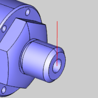
Next we utilize a view option that helps us select a surface edge that is inside of the model.
3 Press the S key, to turn off the Shaded view. (Alternatively, in the View menu, click Shaded.)
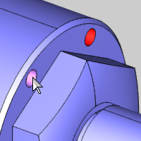
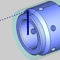
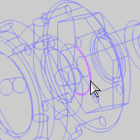
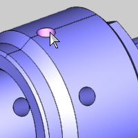
4 Click to select the surface edge (at the bottom of the front hole) as shown next.
This selects the depth point for our feature and automatically sets the Total Depth from the selected geometry.
There is no need to confirm the selection, the software returns to the wizard as soon as you click the edge.
5 Click Next>> to go to the Feature Settings.
Notice that our Total Depth (1.7747) is automatically set from our geometry selection.
1 Under Feature Parameters, change the Diameter value to 0.500.
Under Parameters and Hole Type, click Blind.
2 Click Next>> to go to the Machining Strategy.
3 Under Template, click Hole.
4 Under
Current Operations, with Lathe Center Drill selected, and
click (Delete Operation).
The Current Operations list now contains one Lathe Drill operation.
5 Click Next>> to go to the Posting settings.
6 Under Posting Parameters, click the down arrow and select Canned Cycles.
7 Click Next>> to go to the Tool settings.
1 Click Tool Crib and confirm that the 1/2 Drill tool is selected under Station #19 (the third station of the lower turret).
2 Click OK to close the Tool Crib, and click Next>> to go to the Parameters.
3 Under Cycle Type, click Peck.
4 No other changes are needed for this operation. Click Compute to create the toolpath.
You can turn the Shaded view back on by pressing the S key or using the View menu. You can also press the T key to turn on the transparent view and make it easier to view the toolpath inside the part. (Note then when using keyboard shortcuts, you may need to click anywhere in the graphics area first to give it key focus.)
1 Simulate the feature using the steps explained earlier to confirm the desired result.
2 Close the simulation.
3 You can now hide the toolpath and collapse the feature as explained earlier.
Watch Video - How to Create a Lathe Hole Feature
The next three features that we create use the UT_MS (upper turret, main spindle) submachine, so we want to change the default submachine again. Changing the submachine this time is slightly different than the first time as features already exist, so we are prompted to confirm which features we want to change.
1 Under Machine Setup - 1, right-click the current submachine name (LT_MS), and click Edit.
2 Under Submachine Name, click the down arrow, and select UT_MS.
3 Click OK to update the default submachine.
4 A message displays to ask whether or not we want to change the submachine in existing features. We only want to change the default submachine for new features, so we click No.
All new machining features we create under Machine Setup - 1 now use the new submachine. The submachine can always be changed in the Posting page of the wizard.
The next feature that we create cuts the hex on the front of the part using a single operation to remove the material that remains after our turning operation. Again, we alter the tool assignment so that we can use a finish tool with a rough operation type. (This is done for illustrative purposes, as otherwise you could use a profile finish operation to accomplish the same task.)
1 Right-click Machine Setup - 1, point to Mill Features, and click Mill 2 Axis.
2 Click
Select Geometry.
The Feature Geometry
Picking dialog appears with the focus on the Selected
Geometry list to allow you to select geometry for the feature.
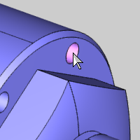
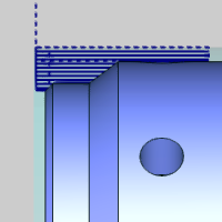
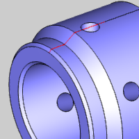
3 Point to the surface at the bottom of the hex so that the surface edge highlights.
Right-click the edge (while it is highlighted) and click Constant Z to select a loop.
1 In
the Profile Chains list, select
Chain-1.
The Chain highlights in the graphics area and the start point and the direction
of the chain are shown as an arrow.
2 Next
to the Profile Chains list, click ![]() (Reverse Direction) to reverse the direction of the chain.
(Reverse Direction) to reverse the direction of the chain.

Next we use the pick buttons to update the Top of Feature and Total Depth values for the feature.
3 Under
the Feature Parameters, in the
Top of Feature group, click in
the Pick Top list to give it focus.
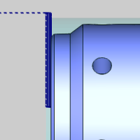
4 Click
on the top of the edge of the model to set that as the top of the feature.
Selecting Top Edge |
Top Edge Selected |
 |
 |
 |
 |
The Top
of Feature updates along with the preview, and focus is shifted
to the Pick Bottom list
of the Total Depth group.
5 Click
any edge of the surface under the hex.
The Total Depth updates along with
the preview.
6 In
the graphics area, right-click and select OK,
or in the Feature Geometry Picking dialog, select OK
to confirm the selections.
The Feature Geometry Picking dialog disappears and the Mill 2 Axis Wizard
returns on the Geometry Selection page.
7 Click Next>> twice to go to the Machining Strategy page.
1 The
default template, Profiling, doesn't need changed, but we remove our finish
operation.
Under Current Operations, click
to select Profile Finish, and
click (Delete Operation).
2 Click Next>> twice to go to the Posting settings. (We are not using Tabs.)
3 Under Posting Mode, click Polar Interpolation.
IMPORTANT: Polar Interpolation is a mode in which the code is posted using XYZ coordinates that are then converted by the machine controller to XZC coordinates. This setting can be used to create more accurate machining and superior surface finishes compared to longhand code, but the machine controller must support Polar Interpolation and be configured to use it.
4 Click Next>> twice to go to the Tool settings. (We do not change the Multiaxis Posting settings).
The following tool assignment is another example of changing tool categories to select a tool from a different category (finish tool for a rough operation type).
1 Click Tool Crib.
2 Under Tool Category, click Endmill Finish to filter the tools list.
3 Click to select the only tool in the tools list, 1/2 Flat Endmill - Long, and click OK.
4 On the left under Profile Rough, click Parameters.
5 Change the Side Allowance value to 0.000, because we are only using a single operation.
6 Click Next>> to go to the Leads settings.
Under Lead-in, click Blend. (Notice that our lead-out is also set to use the same settings.)
7 Click Compute.
It is suggested that you simulate the program after each feature you create. This makes it much easier to find mistakes and resolve them immediately.
1 On
the Other toolbar, click the  Simulation button.
Confirm that no changes are needed by running the simulation. Note again that you can use the Move List to go directly to the operation you are verifying.
You can also use the Report tab to check for any reported collisions during the simulation. Note that when you click an operation in the Move List (called manual navigation), no collision detection is performed for the operations that were skipped and a warning message displays in the Report tab.
2 Close the simulation.
3 Hide the toolpath and collapse the feature.
Watch Video - How to Create a Mill 2 Axis Feature - Face Milling
Next we create a Mill Drill Hole feature to drill the circular hole pattern on the face of the model. For Mill Turn jobs, this is called face or standard drilling (the tool is parallel to the Z-axis).
1 Right-click Machine Setup - 1, point to Mill Features, and click Mill Drill Hole.
2 Click Select Geometry.
Notice in the Hole Selection Manager that the default drilling type is Standard Drill, which is used for drilling along the Z-axis. Be sure to select the appropriate drilling type before confirming your geometry selections.
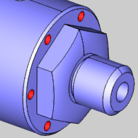
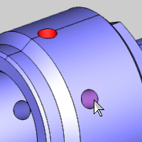
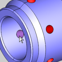
3 Click to select the six cylindrical surfaces of the holes as shown next.
4 Click
(OK), to confirm the selection.
TIP: Selecting cylindrical surfaces allows the software to automatically detect and set the Feature parameters in the wizard for you.
5 In the Holes list, click to select the only hole item (0.25 Diameter).
Under Geometry Parameters, click to clear the Through Hole check box, because these holes do not go through the entire model.
Notice that our Diameter and Depth are automatically set to the correct values.
6 Click Next>> to update the wizard tree.
In the Feature page, we can see that the software automatically set the Diameter, Top of Feature, and Total Depth because we selected cylindrical surfaces. The software also automatically creates Hole Groups for all holes with these same feature parameters. This feature results in a single hole group.
1 Click the Group Retracts button, you can see that the Clearance Plane Height value is automatically set based on our geometry selection, clearance settings, and machining origin (work offset) position. (Click OK to close the dialog box.)
The Group Retracts determine the rapid movement to clearance between hole groups, not within them. For our rapid movement between holes, we use the Rapid Plane. For this model, we need to increase our rapid plane to clear the boss in the center of the model.
2 Change the Rapid Plane value to 0.7500.
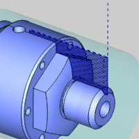
Under Hole Groups, click anywhere in the row of Group 1 to select it and display the hole groups preview directly inside the wizard.
The Hole Groups preview is very helpful in confirming the proper selections and feature parameters. Again, more information is available in this help system.
3 Click Next>> to go to the Machining Strategy.
4 Under Template, click Hole.
Under Current
Operations, click to select Center
Drill, and click (Delete
Operation).
5 Click Next>> to go to the Posting settings.
Under Posting Mode, click Longhand Code.
This posting mode uses C-axis motion to drill the holes, as compared to the Auto/Y Axis Mode which uses Y-axis movement to drill the holes. If the submachine does not have Y-axis capability, Auto/Y Axis Mode and Longhand Code produce the same result.
6 Click Next>> twice to go to the Tool settings. (We do not change the Multiaxis Posting settings).
1 Click Tool Crib and confirm the appropriate tool (1/4 Drill) is automatically assigned.
Click OK.
2 Click Next>> to go to the Parameters.
Notice the Hole Groups list here, when changing the parameters for hole groups, it is important that you select a group in the list before changing any settings. For this example, we use the default parameters.
3 Click Compute.
4 Simulate the feature, hide the toolpath, and collapse the feature.
Watch Video - How to Create a Mill Hole Feature - Face Drilling
Our next feature cuts a groove on the OD of the part. This is the last operation that we perform using the main spindle, before creating our part transfer to the sub spindle. We create our grooving operation first and then edit the feature to add our part transfer using MDI (manual data input).
1 Right-click Machine Setup - 1, point to Turn Features, and click Lathe Turning.
2 Click Select Geometry.
3 In the Layers Manager, right-click Groove, and click Show.
4 Right-click the CAD layer and click Hide to hide the model.
5 Click and drag to select the groove geometry in the graphics area.
6 Click
to confirm the selection.
7 Click Next>> twice to go to the Machining Strategy.
1 Under Template, click Turn Groove.
2 Under
Current Operations, click to select
the Turn Groove Finish operation,
and click .
3 Click Next>> to go to the Posting settings.
4 Change the Posting Parameters to Canned Cycles.
5 Click Next>> to go to the Tool settings.
1 Again, we can see the appropriate tool (1/8 OD Groove) is already assigned. You can open the Tool Crib to confirm the appropriate settings for the tool if desired.
2 Click Next>> to go to the Parameters.
3 Under Parameters, make the following changes:
Stepover = 0.1250
Z Allowance = 0.00
X Allowance = 0.00
Because we are using a single operation to cut the groove, we remove the allowances. Also note that our stepover value is not critical for this feature as the tool and the groove are the same size.
4 In the tree on the left, click Leads.
5 Under Lead-in, change the Lead-in X value to 0.100.
6 Click Compute.
(You can show the CAD layer and hide the Groove layer as well.)
7 Simulate the feature, hide the toolpath, and collapse the feature.
Watch Video - How to Create a Turning Feature - OD Grooving
For Mill Turn jobs, the MDI page of the wizard allows you to manually define machine movements by combining commands to create lines of code. This is used to handle machine axes movements that do not have a specific operation, such as part transfers, cutoff/transfer, parts catchers, steady rests, and tailstocks. We define our part transfer after the grooving operation as it is the last operation we perform on the main spindle before transferring the part to the sub spindle.
NOTE: When you purchase the Mill Turn module from BobCAD-CAM, the Posting department will work with you to create your own generic MDI files (templates) that are customized for your machine to handle transferring the part from the main spindle to the sub spindle. The expected workflow is to define a process once using MDI, save it to a file, then simply load the saved file and change a few values as needed per job. We do the same for this example using the generic part transfer MDI file that is installed with the software.
1 In the CAM Tree, right-click the last Feature Lathe Turning feature (that we just created), and click Edit.
The Lathe Wizard displays for you to make changes to the feature.
2 In the tree on the left, click MDI.
3 Notice
the Save/Load group under the
Task List. Click the  (Load) button.
The Open dialog box should display with the correct location already selected: C:\BobCAD-CAM Data\BobCAD-CAM V28\Features. If not, navigate to this folder.
4 Click to select GenericPartTransfer.bcmdi and click Open. (Alternatively, you can double-click the file name to open it.)
The Load MDI Task dialog box displays. This dialog box allows you define exactly what tasks are overwritten with the information from the file. This allows you to load individual tasks from the saved file, but for this example, we use the full replace.
5 Click OK to replace the entire current Task List with the information stored in the file.
You can see that only the After Operation task contains any commands (it has the plus sign icon). Click the plus sign to expand the After Operation folder and view all the lines that are already defined. All of our commands are under the After Operation task, because our part transfer happens after the grooving operation.
6 We don't need to make any changes to our generic MDI parameters, but a few of the important commands that you may adjust per job are listed next. This is shown in the video as well as how to modify the values for a command.
Important Command Values:
Command |
Value |
Orient Main Spindle |
Angle |
Orient Sub Spindle |
Angle |
Move Sub Spindle to Clearance |
Axis |
Start Fast Feed Up to Part |
Axis and Feedrate |
Feed to Pickup Location |
Axis and Feedrate |
Part Transfer |
Part Pickup Position |
Send Sub Spindle Home |
Work Offset and Axis |
Note that the number of parameters that you need to adjust depends on the way you work. Many of these values may never be changed from the values defined in the MDI template file.
You modify commands on the MDI page using the Parameters group. The general process is as follows:
Expand a  Task
to view the Lines under it.
Task
to view the Lines under it.
Expand a  Line
to view the Commands under it.
Line
to view the Commands under it.
Click to select a  Command.
All available parameters display under Parameters at the bottom of the MDI page.
Update the values as needed. (The changes you make are reflected in the Task List.)
7 Click Finish to update the feature with the MDI part transfer.
Our part transfer is now output in the code, and is also visible in simulation (without MDI, in simulation the part just switches spindles without showing the transfer movement).
Watch Video - How to Create a Part Transfer with MDI
8 Simulate the program to view the part transfer.

Now that the part is transferred to the sub spindle, all of our machining features for the second half of the part are created under Machine Setup 2, which is set to Work Offset 2. Most of the remaining features use the UT_SS (upper turret, sub spindle) submachine, so we set the default submachine for creating features under Machine Setup 2.
1 Expand Machine Setup - 2 (if needed), right-click the current submachine name UT_MS, and click Edit.
2 Change the Submachine to UT_SS (upper turret, sub spindle), and click OK.
3 You can also collapse Machine Setup 1 to minimize the CAM Tree and reduce the need for scrolling.
Now we begin to machine the back half of the part by creating another facing cycle to cut the stock to zero.
Next we begin to create features under Machine Setup 2 to machine the back half of the part. If you would like to learn how to define this machine setup, view the Mill Turn Job Setup Example.
1 In the View menu, point to Views, and click ISO 3.
This is the main viewing orientation we use while creating the features for the back of the part. (In the video, you can see that the instructor created custom shortcut keys to make using this view easier.)
1 Right-click Machine Setup - 2, point to Turn Features, and click Lathe Turning.
2 Click Select Geometry.
In the Layers Manager, show the Back Face layer.
TIP: You can turn off the Shaded view to make it easier to select the line geometry which is in front of the solid model.
Click to select the line, and click .
3 Click Next>> twice to go to the Machining Strategy.
1 Under
Current Operations, click Face Basic Finish, and click .
(We are using the default Template Face Rough.)
2 Click Next>> to go to the Posting settings.
3 Under Posting Parameters, click the down arrow and select Canned Cycles.
4 Click Next>> to go to the Tool settings.
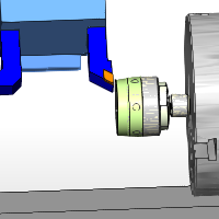
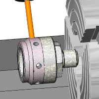
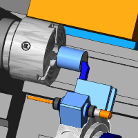
1 Confirm that the 55 Deg. 1/32 Rough Turning tool is selected under Tool Data. (As always, you can open the Tool Crib to confirm the proper tool selection and mounting).
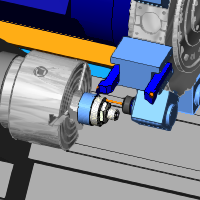
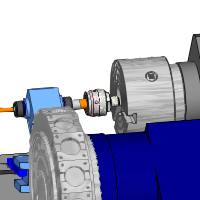
The following image shows the tool we select (it is highlighted with the yellow holder). You can see that the tool is mounted with the correct orientation for machining the back side of the part (on the sub spindle).
2 Click Next>> to go to the Parameters.
3 Under Parameters, make the following changes:
Depth of Cut = 0.0350
Z Allowance = 0.00
X Allowance = 0.00
4 In the tree on the left, click Leads and make the following changes:
Lead-in X = 0.100
Lead-out Z = 0.100
5 Click Compute.
6 Simulate the feature and confirm that no changes are needed.
7 Hide the toolpath and collapse the feature.
Watch Video - How to Create a Lathe Turning Feature - Facing
The next feature is created to rough and finish the remaining stock material on the back half of the part.
1 Right-click Machine Setup - 2, point to Turn Features, and click Lathe Turning.
2 Click Select Geometry.
3 Show the layer Back Turn.
In the Edit menu, point to Select Entities, and click Pick By Layer.
In the Select Layer dialog box, click Back Turn, and click OK.
4 To
confirm the selection, click .
5 Click Next>> twice to go to the Machining Strategy.
1 Under Template, click Turn Rough.
The Current Operations list now displays one Turn Rough operation and one Turn Basic Finish operation.
2 Click Next>> to go to the Posting settings.
3 Under Posting Parameters, click the down arrow and select Canned Cycles.
4 Click Next>> to go to the Tool settings.
1 Confirm that the 55 Deg. 1/32 Rough tool is selected under Tool Data.
2 Click Next>>.
3 Under Parameters, make the following changes:
Depth of Cut = 0.0350
Z Allowance = 0.0030
4 Click Next>> twice to go to the Leads settings and make the following changes.
Lead-in Z = 0.100.
Lead-out Z = -0.050.
TIP: Notice that we used a negative lead-out, which creates an overlap in the toolpath where the front turning operation and back turning operation meet. (The toolpath extends past the selected geometry.)
5 Click Apply to All Operations.
1 Under Turn Basic Finish, click Finish.
2 Click Tool Crib.
3 Under Tool Category, click Lathe Rough.
4 Click to select the 55 Deg. 1/32 Rough Turning tool in the tool list, and click OK.
5 Click Compute.
6 Simulate the program and confirm the desired result.

7 Hide the toolpath, collapse the feature, and save the file.
Watch video - How to Create a Lathe Turning Feature - OD Turning
The next feature drills a large hole in the back of the part to prepare it for the boring operation we create afterwards. Our drill for this operation is on the lower turret, so this feature provides an example of changing the submachine for the feature using the Posting page. (This is the only feature under Machine Setup 2 that doesn't use the UT_SS submachine.)
1 Right-click Machine Setup - 2, point to Turn Features, and click Lathe Hole.
2 Click Select Geometry.
3 Press S to turn off the Shaded view, and click to select the surface edge as shown next.
The wizard returns when you click the edge.
4 Click Next>>.
1 Notice that our Total Depth is automatically set (2.000) from our geometry selection.
Update the Diameter value to 1.2500.
Under Hole Type, click Blind.
2 Click Next>>.
3 Under Template, click Hole.
Delete the Lathe Center Drill operation from the Current Operations list.
4 Click Next>>.
5 Under Posting Parameters, click the down arrow and select Canned Cycles.
6 Change the Submachine to LT_SS (lower turret, sub spindle).
7 Click Next>> to go to the Tool settings.
1 Click Tool Crib.
2 Confirm that the 1.250 Dia. 118 Deg. tool is selected, and click OK.
3 Click Next>>.
4 Under Cycle Type, click Peck.
5 Click Compute.
Hide the toolpath and collapse the feature. You can also turn on the Shaded view.
6 Simulate the feature.
Watch Video - How to Create a Lathe Hole Feature
Next we create a boring feature to finish clearing the material on the inside (ID) of the part.
IMPORTANT: When creating Turning features for boring, it is important that you select a boring tool (a tool from the boring category) in order to create proper simulation of the operation. (The boring tool type is handled differently in simulation.)
1 Right-click Machine Setup - 2, point to Turn Features, and click Lathe Turning.
2 Click Select Geometry.
3 Hide the CAD layer and show the Back ID/Boring layer.
4 Click and drag a window to select the profile.
5 You
can show the CAD layer, and then
click .
6 Click Next>>.
1 Under Parameters, change the Internal Diameter value to 1.2500.
We change this value to adjust the first depth of cut to start where the material from the drilling operation remains.
2 Click Next>>.
3 Select the Turn Rough template, and click Next>>.
4 Change the Posting Parameters from Separate Moves to Canned Cycles.
5 Click Next>>.
1 Click Tool Crib.
2 Under Tool Category, click Lathe Boring to filter the tools list.
3 Select the only tool in the tools list, 80 DEG 1/64 CRAD 1 INCH BORING BAR.
4 Click OK to assign the tool to the operation.
Click Next>>.
5 Update the Parameters as follows:
Depth of Cut = 0.0400
Z Allowance = 0.0030
6 Click Next>> twice, and update the Leads settings as follows:
Lead-out X = 0.050
Click Apply to All Operations
1 Under Turn Basic Finish, click Finish to go to the Tool settings.
2 Click Tool Crib.
3 Under Tool Category, click Lathe Boring.
4 Select 80 DEG 1/64 CRAD 1 INCH BORING BAR and click OK.
You can check the Leads settings of the finish operation to confirm that they are the same as the rough.
5 Click Compute.
6 Hide the toolpath, collapse the feature, and hide the boring geometry (Back ID/Boring layer).
7 Simulate the feature.
Watch Video - How to Create a Lathe Turning Feature - (ID) Boring
For the final operation, we create a drilling feature to handle the cross drilled holes in the model. Cross (or radial) drilling means that the tool axis crosses the center line of the part (the tool is parallel to the X-axis). What is important here is selecting the drilling type, Cross Drill, in the Hole Selection Manager.
1 Right-click Machine Setup - 2, point to Mill Features, and click Mill Drill Hole.
2 Click Select Geometry.
3 In the Hole Selection Manager, next to Standard Drill, click the down arrow and select Cross Drill.
IMPORTANT: When selecting geometry for Mill Drill Hole features, it is important to select the proper drilling type based on the orientation of the holes, as the software filters your selections accordingly. (Standard Drilling is parallel to Z-axis, Cross Drilling is perpendicular to [and intersects or crosses] the selected Rotation Axis, and Multiaxis Drilling is any orientation.)
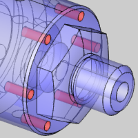
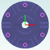
4 Click to select the six cylindrical surfaces of the holes on the outside diameter of the part.
5 Click
(OK), to confirm the selection.
6 Click Next>> to go to the Feature settings.
1 Under Material Approach, click Group Retracts.
Notice that our clearance Type is automatically set to Cylinder and the Radius value is 1.8500. The software automatically selects a cylindrical clearance for cross drilling and sets the Radius value based on the stock and clearance settings from the Stock Wizard and Machine Setup. (Note that the Group Retracts handle the clearance movement between hole groups and not within them. The Rapid Plane determines the rapid clearance movement within hole groups.)
2 Click OK.
3 Under Hole Groups, click anywhere in the row of Group 1 to select it and display the hole groups preview inside of the wizard.
Using the Hole Groups preview is a great way to confirm the proper feature settings before computing the toolpath.
Notice the Diameter, Top of Feature, and Feature Depth values are all automatically set because we selected cylindrical surfaces.
4 Click Next>>.
5 Select the Hole template, and delete the Center Drill operation from the Current Operations list.
Click Next>> to update the wizard tree with the new template.
6 Under Drill, click Drill to go to the Tool settings.
You can open the Tool Crib to confirm that the assigned tool is indeed mounted for cross drilling. It is important that you select a tool in the proper orientation for the operation you are creating.
Confirm that the 3/8 Drill tool is selected and click OK.
7 Click Compute.
Watch Video - How to Create a Mill Hole Feature - Cross Drilling
Now that all of our features are created to machine the entire part, we can simulate the program to confirm the desired result for the entire job.
IMPORTANT: For Mill Turn Jobs, you cannot post or simulate the program unless all tools are mounted in the Tool Crib. For example, when the software cannot find the appropriate tool in the Tool Crib during tool assignment, it assigns a tool from the Tool Library and places it under the Loose tools item in the device tree. Loose tools are tools that are assigned to an operation, but not mounted. All Loose tools must be mounted before simulating or posting. You can open the Tool Crib to confirm there are no unmounted (Loose) tools before simulating or posting the program.
1 In the CAM Tree, right-click Mill Turn Tools, and click Tool Crib.
Note that when you open the Tool Crib from the CAM Tree, all tool devices on the machine display in the device tree.
2 In the device tree on the left, drag the slider down to view the Loose tools and confirm there are none. Note that there is one Loose tools item per device, so be sure to check both (all) devices for Loose tools.
TIP: BobCAD-CAM uses a special convention for Loose (unmounted) tools. The Tool Number for loose tools is -1 (negative one). When you see a tool with a tool number of -1, you know that you need to mount it (or assign a different tool to the corresponding operation). The easiest way to see where a loose tool is assigned is to open the Assigned Tools dialog box (right-click Mill Turn Tools, and click Verify Tool Assignment). This dialog box lists all features to which each tool is assigned.
3 For our example, there are no loose tools, so we are ready to simulate the program.
4 Right-click Mill Turn Job, and click Simulation.
For more help using simulation, view Getting Started with Simulation.
Mill Turn jobs contain three different methods for defining the tool numbering. The default method (Use Station #) automatically numbers the tools based on the station to which they are mounted. This is commonly used on machines that contain one or more turrets and is also adapted to work well for 5-axis applications in which the machine is equipped with a milling head. The second method (Use Tool ID) utilizes the Tool ID to guarantee a unique number is assigned to each tool. The final method (Manual) provides a completely user-defined or manual tool numbering scheme in which the software loads the tool number stored in the Tool Library, which you can modify as needed.
The following steps show you how to confirm proper tool numbering after creating all features for the job. (Note that you can also define your tool numbering while you create the job, as the same options are available in the Tool Crib.)
1 In the CAM Tree, right-click Mill Turn Tools, and click Verify Tool Assignment.
The Assigned Tools dialog box displays. This dialog box lists all tools that are actually used in the job (assigned to an operation) and lists various information about them.
2 Confirm the appropriate tool numbering for the job and make any changes as needed.
IMPORTANT: The tool offset numbers for each operation are set in the Tool page of the CAM wizards. The BobCAD-CAM software always sets the offset numbers to match the tool number unless you use Override Offsets to define the offset number manually.
3 After confirming all tool numbering, click OK to close the dialog box.
After simulating the program and confirming our tool numbering, no changes are needed so we are ready to post the program and create the NC program (G-Code).
1 Right-click Mill Turn Job, and click Post. (Alternatively, you can click Post and Save As if you would like to select a different location to which the file is saved. The default location is the BobCAD-CAM Data NC folder.)
The NC program displays in the Posting tab of the Layer-UCS-Post Manager.
2 You can view the code from this location, and you can also right-click anywhere in the window to access another shortcut menu, for example, for opening the code in the Editor.
3 Save the file.
Congratulations! You have completed the Mill Turn Example 1 tutorial. Much more information about Mill Turn jobs is available in this Help system.