In this Topic Show
This example explains how to use the Break option in the Edit Toolpath dialog box. On our example part, we have used a solid model to set the stock to a specific shape. In this case, the stock shape shows what the first two operations have left. Due to the size of the rough tool, much more material has been left in the acute angles of our pocket. It is because of this, it would be beneficial to slow down the feedrate on our finish operation before it engages that extra material. To accomplish this, we will need to break the toolpath elements leading into, and out of, our acute angles. Once this is accomplished, we can adjust the feedrate on the specific portions of toolpath that engage the leftover material, which will be accomplished in another example. This example will have you:
The part file for this example is available for download at: http://bobcad.com/helpfiles. If you are connected to the Internet, you can click the link provided to download and save the Toolpath_Editor_Break_Example BBCD.zip file. After extracting the zip file, you can open the file to follow along with this example. In the example file provided, the stock and Machine Setup are already defined for the part, and the toolpath to be adjusted has been applied.
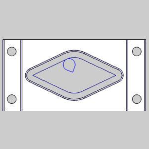
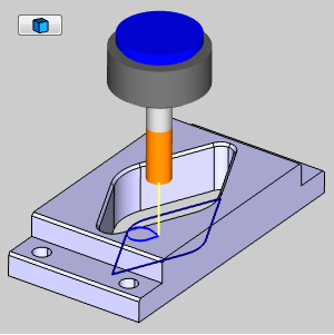
Take a moment to look at the stock compared to the existing toolpath to see the what we intend to accomplish.
1 In
the Data-CAM
Tree Manager,
click the  CAM
Tree tab.
CAM
Tree tab.
2 In
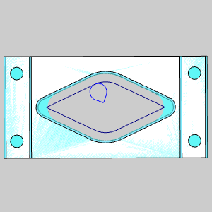
the CAM Tree, click ![]() Stock to view the assigned stock.
Stock to view the assigned stock.
Take a moment to look at the existing stock compared to the existing toolpath
to get an idea of where we would like to break our toolpath elements.
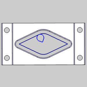
3 In
the CAM Tree, click the Pocket operation in the feature to remove focus
on the stock and to place focus on the toolpath to be adjusted.
The Edit Toolpath function is only applied to individual operations, as such, the first step is always to right-click on the operation to be adjusted.
1 Right-click
the Profile Finish operation of the second Feature 2 Axis.
2 Select
Edit Toolpath.
The Edit
Toolpath dialog appears.
The Edit Toolpath dialog gives you access to eight different Command Modes. For this example, we will be utilizing the Break Command Mode.
1 Click
the arrow on the Command Mode
list to view the list items.
2 Select
the Break option.
3 By default, the Preview check box is already selected. Leave this check box selected, as it will allow us to see a preview of the executable result.
Change Parameters to the Screen Point option.
1 Select the Screen Point option in the Parameters group.
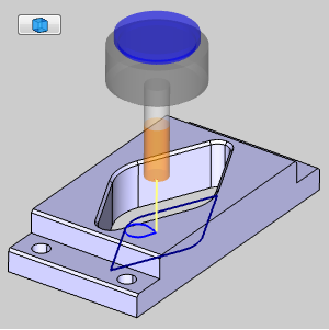
Select the toolpath to be edited.
1 In the graphics area, select
the toolpath shown in the images below.
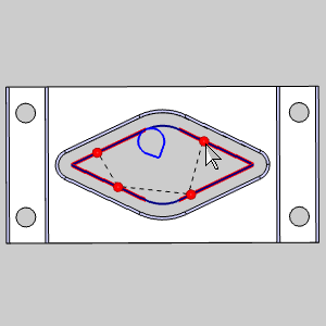
With the toolpath elements selected, we will need to define the distance of the Break Point.
1 In
the Break Point list, select Break Point
- 1.
Break Point - 1 highlights in the graphics area.
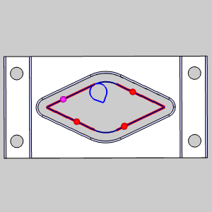
2 Change
the Distance to 70.
3 In
the Break Point list, Select Break Point
- 2.
Break Point -1 adjusts its position in the graphics area and Break Point
- 2 highlights.
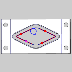
4 Change
the Distance to 30.
5 In
the Break Point list, Select Break Point
- 3.
Break Point -2 adjusts its position in the graphics area and Break Point
- 3 highlights.
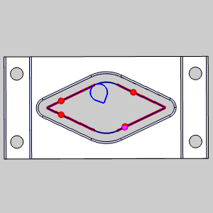
6 Change
the Distance to 70.
7 In
the Break Point list, Select Break Point
- 4.
Break Point -3 adjusts its position in the graphics area and Break Point
- 4 highlights.
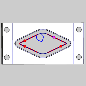
8 Change the Distance to 70.
To move beyond the preview, and before clicking OK to finalize and exit, it is a good idea to Execute the current settings. Although clicking OK will Execute and exit simultaneously, using Execute will allow you to use Animation to verify the results and Undo the executed command if and adjustments necessary.
1 Click
Execute.
The toolpath elements update.
The Animation is an excellent way to double check the edits we have made to our toolpath elements. If any issues are noticed in the animation, we can easily undo our edits and make the necessary adjustments.
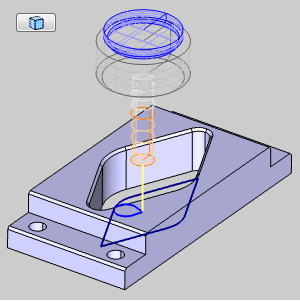
1 Select
the check box for Animation.
The tool appears in the graphics area at the start of our toolpath.
2 Use
the Animation controls to play through the animation. With either the
![]() (Solid),
(Solid),
![]() (Transparent),
or
(Transparent),
or ![]() (Wireframe)
view.
(Wireframe)
view.
Once the Animation has been viewed to ensure no further edits are needed, click OK to finalize and exit the Edit Toolpath Dialog. If you need to change the toolpath to its original state after clicking OK, recompute the operation.
1 Click
OK.
The Edit Toolpath Dialog closes.
This concludes this example.