In this Topic Show
This example explains how to use the Move option in the Edit Toolpath dialog box. The Move command will allow you to select particular toolpath elements and adjust their position. The example provided will have you:
The part file for this example is available for download at: http://bobcad.com/helpfiles. If you are connected to the Internet, you can click the link provided to download and save the Toolpath_Editor_Move_Example BBCD.zip file. After extracting the zip file, you can open the file to follow along with this example. In the example file provided, the stock and Machine Setup are already defined for the part, and the toolpath to be adjusted has been applied.
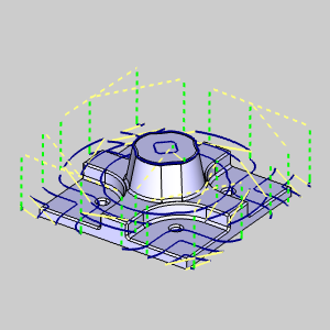
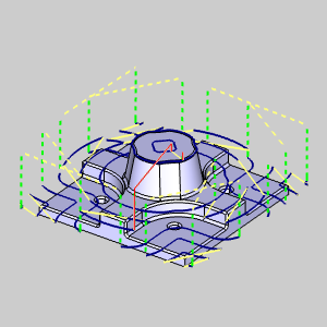
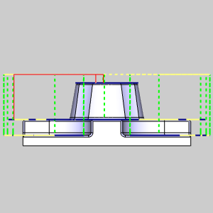
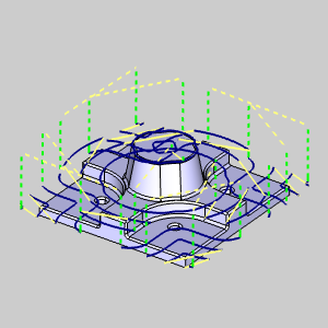
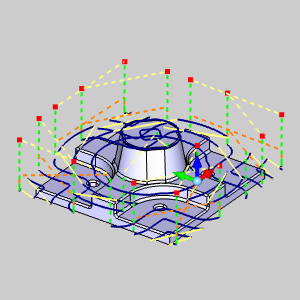
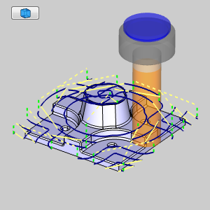
On our example part, we have used a solid model to set the stock to a specific shape. In this case, we have roughed out the stock with an Advanced Rough and have finished that up with a Flatlands toolpath. It is the rapid heights of the Flatlands toolpath we intend to adjust. Take a moment to notice there is only two rapids, highlighted in red in the images below, that need to be at their current height.
1 In
the Data-CAM
Tree Manager,
click the  CAM
Tree tab.
CAM
Tree tab.
2 In
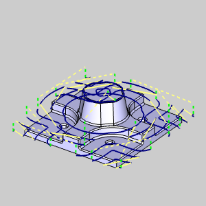
the CAM Tree, click the ![]() Flatlands operation
of the
Flatlands operation
of the ![]() Feature 3 Axis
to highlight the toolpath in the graphics area.
Feature 3 Axis
to highlight the toolpath in the graphics area.
Take a moment to look at the existing stock compared to the existing toolpath
to see what we intend to accomplish.
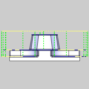
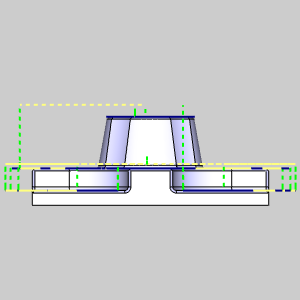
3 Rotate
the part into a side view.
Notice most of these rapid moves could be lower to save some machining
time.
The Edit Toolpath function is only applied to individual operations, as such, the first step is always to right-click on the operation to be adjusted.
1 Right-click
the ![]() Flatlands
operation of the
Flatlands
operation of the ![]() Feature
3 Axis.
Feature
3 Axis.
2 Select
Edit Toolpath.
The Edit
Toolpath dialog appears.
The Edit Toolpath dialog gives you access to eight different Command Modes. For this example, we will be utilizing the Move Command Mode.
1 Click
the arrow on the Command Mode
list to view the list items.
2 Select
the Move option.
3 By default, the Preview check box is already selected. Leave this check box selected, as it will allow us to see a preview of the executable result.
We now, need to select the Point Pick check box under the Selected Toolpath Elements list so that we can pick the points where the vertical and horizontal rapids meet. Once this is selected, we will move the rotate the part, as needed, to pick all sixteen toolpath points shown in the images below.
1 Under the Selected Toolpath
Elements list, select the Point Pick
check box.
This will allow us to pick the point at which two toolpath elements meet,
thereby giving us the ability to adjust both elements, rather than just
one element or the other.
2 In
the graphics area, select the toolpath points shown in the image below.
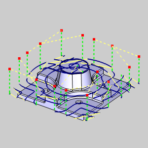
In each of the four corners of the part, there are two rapids. Be sure
to pick both points on each of the eight rapid moves.
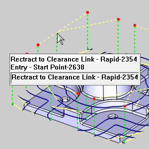
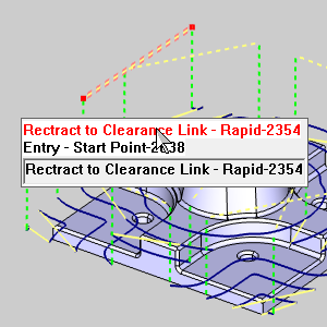
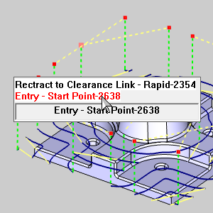
NOTE: When toolpath elements are close enough together, attempting to select one may cause a dialog to appear. This dialog will allow you to select, from the dialog list, the intended toolpath element, as seen in the images below.
With the toolpath elements selected, we will need to set the Parameters to define how the selected toolpath elements will be moved.
1 In
the Parameters group, select the
Drag option.
The Drag handles appear in the graphics area.
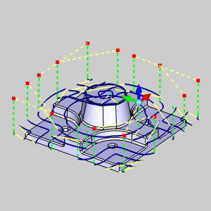
2 Click
the Z Axis of the Drag Handle.
The Z Axis highlights.
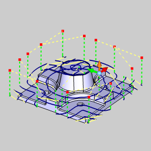
3 With
the Z Axis highlighted, move your mouse up and down and notice the preview
adjust.
While the X,Y, and Z values can be adjusted visually, we will enter a value
in the Delta Z text field.
4 In
the Delta Z text field, enter -1.0.
The preview updates to show the executable result.
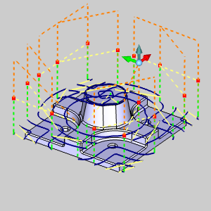
To move beyond the preview, and before clicking OK to finalize and exit, it is a good idea to Execute the current settings. Although clicking OK will Execute and exit simultaneously, using Execute will allow you to use Animation to verify the results and Undo the executed command if and adjustments necessary.
1 Click
Execute.
The toolpath elements update to show the effect of our edits.
The Animation is an excellent way to double check the edits we have made to our toolpath elements. If any issues are noticed in the animation, we can easily undo our edits and make the necessary adjustments.
1 Select
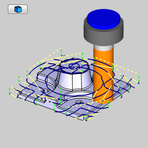
the check box for Animation.
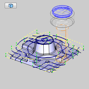
The tool appears in the graphics area at the start of our toolpath.
2 Use
the Animation controls to play through the animation. With either the
![]() (Solid),
(Solid),
![]() (Transparent),
or
(Transparent),
or ![]() (Wireframe)
view.
(Wireframe)
view.
Once the Animation has been viewed to ensure no further edits are needed, click OK to finalize and exit the Edit Toolpath Dialog. If you need to change the toolpath to its original state after clicking OK, recompute the operation.
1 Click
OK.
The Edit Toolpath Dialog closes.
This concludes this example.