In this Topic Show
This example explains how to use the Replace option in the Edit Toolpath dialog box. The Replace command mode will allow you to substitute wireframe and/or edge geometry for existing toolpath elements. The example provided will have you:
The part file for this example is available for download at: http://bobcad.com/helpfiles. If you are connected to the Internet, you can click the link provided to download and save the Toolpath_Editor_Replace_Example BBCD.zip file. After extracting the zip file, you can open the file to follow along with this example. In the example file provided, the stock and Machine Setup are already defined for the part, and the toolpath to be adjusted has been applied.
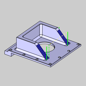
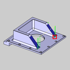
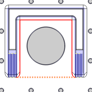
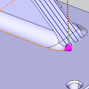
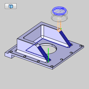
On our example part, we have created an Advanced Planar toolpath, and have used boundaries to isolate it on the angled surfaces of our part. In this case, the toopath has been separated into two separate regions, and those regions are connected with a rapid. It is this rapid we will replace with a feed move that traces around the inner fillet in the direction seen below.
1 In
the Data-CAM
Tree Manager,
click the  CAM
Tree tab.
CAM
Tree tab.
2 In
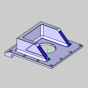
the CAM Tree, click the ![]() Advanced Planar operation of the
Advanced Planar operation of the
![]() Feature 3 Axis
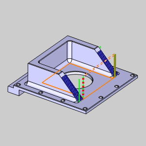
to highlight the toolpath in the graphics area.
Feature 3 Axis
to highlight the toolpath in the graphics area.
Take a moment to look at the existing linking between toolpath regions
to see what we intend to accomplish.
The Edit Toolpath function is only applied to individual operations, as such, the first step is always to right-click on the operation to be adjusted.
1 Right-click
the ![]() Advanced Planar
operation of the
Advanced Planar
operation of the ![]() Feature 3 Axis.
Feature 3 Axis.
2 Select
Edit Toolpath.
The Edit
Toolpath dialog appears.
The Edit Toolpath dialog gives you access to eight different Command Modes. For this example, we will be utilizing the Replace Command Mode.
1 Click
the arrow on the Command Mode
list to view the list items.
2 Select
the Replace option.
3 By default, the Preview check box is already selected. Leave this check box selected, as it will allow us to see a preview of the executable result, once our Toolpath Chain has been confirmed.
Select the toolpath to be edited.
1 In the graphics area, zoom
into the area shown in the image below.
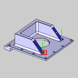
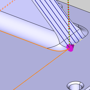
2 Hover
over the lower portion of the retract move and click on the toolpath element
shown below.
Important : If the toolpath elements that highlights is not the first move of the rapid, as in the image below, be sure to include the first toolpath element in your selection as well.
3 Zoom
out in order to bring the entire model back into view.
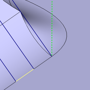
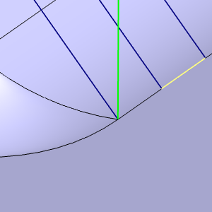
4 Now,
zoom into the area shown in the image below.
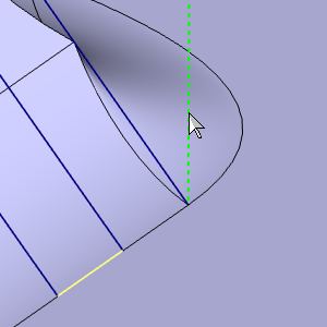
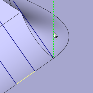
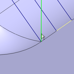
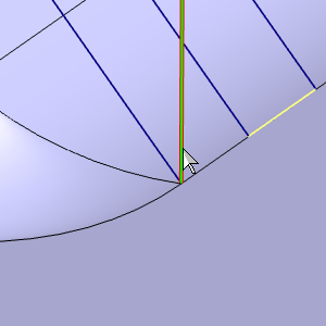
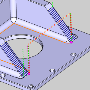
5 Move
your mouse to the end of the green toolpath element.
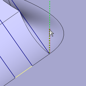
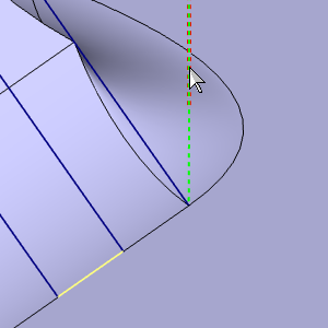
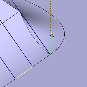
6 Press and hold Shift and
click the bottom of the
toolpath element to perform a chain selection of all the toolpath elements
between.
With the toolpath elements selected, we will need to set the Toolpath Chain to define the new path of the toolpath elements.
1 In
the Parameters group, click the
Pick button to begin selecting
the Toolpath Chain.
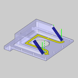
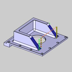
2 Select
the five individual edges on the model, as shown in the images below.
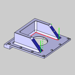
3 With
the five edges selected, right-click and select ![]() OK.
OK.
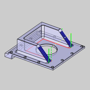
The executable preview displays.
In some cases, depending on the direction of the Toolpath Chain, the preview may show an unintentional result, as shown in the image below. In these cases, we would need to Reverse Direction.
1 In
the Toolpath Chain list, click on Chain
1 to highlight it.
The Chain highlights and shows directional arrows.

2 Right-click
Chain 1 in the Toolpath
Chain list.
3 Select
Reverse Direction.
The chain reverses and the preview updates.
To move beyond the preview, and before clicking OK to finalize and exit, it is a good idea to Execute the current settings. Although clicking OK will Execute and exit simultaneously, using Execute will allow you to use Animation to verify the results and Undo the executed command if and adjustments necessary.
1 Click
Execute.
The toolpath elements update to show the effect of our edits.
The Animation is an excellent way to double check the edits we have made to our toolpath elements. If any issues are noticed in the animation, we can easily undo our edits and make the necessary adjustments.
1 Select
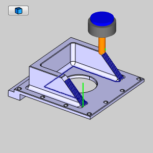
the check box for Animation.
The tool appears in the graphics area at the start of our toolpath.
2 Use
the Animation controls to play through the animation. With either the
![]() (Solid),
(Solid),
![]() (Transparent),
or
(Transparent),
or ![]() (Wireframe)
view.
(Wireframe)
view.
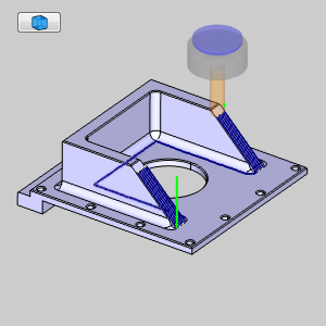
Once the Animation has been viewed to ensure no further edits are needed, click OK to finalize and exit the Edit Toolpath Dialog. If you need to change the toolpath to its original state after clicking OK, recompute the operation.
1 Click
OK.
The Edit Toolpath Dialog closes.
This concludes this example.