This tutorial explains how to create a multi-start thread using the Thread milling feature and a toolpath pattern. The result is a 2-inch diameter I.D. multi-start thread with two start points.
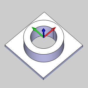
The part geometry for this example is shown next. Stock has been created using the Solid Model option, and the machining origin is placed at the top and center of the stock. Because we are making a 2-inch ID thread, the hole diameter of the part is 1.8125 inches.
There are a few main points to understand when creating Thread Mill features:
1 In
the  CAM Tree,
right-click
CAM Tree,
right-click  Machine
Setup, and click Mill Thread.
Machine
Setup, and click Mill Thread.
2 In
the Geometry Selection page, click
Select Geometry.
The Mill Thread Wizard disappears and the Hole Geometry Picking dialog
launches.
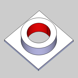
3 Click the inner cylindrical surface of the part model.
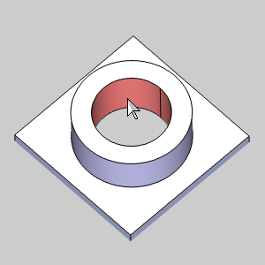
To confirm the selection, click  .
.
4 Click Next>> to start defining the Feature parameters.
1 Set
the desired Rapid Plane and Feed Plane values for the feature.
2 Confirm
that the Hole Type is set to Through Hole.
3 Because the geometry selected was the cylindrical surface, the Top of Feature and Feature Depth value is set based on that surface.
This defines the top and bottom of the thread.
In the Feature Parameters group,
in the Total Depth box, type 1.375.
The part height is 1.25 inches so this assures that the tool continues past the bottom of the part.
4 Click Next>>.
1 For this example, we are only using a single Mill Thread operation.
Confirm that the Current Operations group contains only one Mill Thread operation.
2 The default Machining Strategy is all that is needed, click Next>> to go to the Machine Sequence.
1 Since
we do not have multiple threads, we do not need to set a Sort Order or
Start Location.
Click Next>> to go to the
Posting page..
1 Under Thread Mill Output, select Line Moves or Arc Moves to define what is output in the NC program.
2 Confirm that the proper Work Offset # is selected for the feature.
(If you have a Multiaxis license and a multiaxis machine selected for the job, click Next>> to skip the Multiaxis Posting page.)
3 Click Next>> to go to the Tool settings.
1 In the Tool Data group, define the tool parameters.
For this example, the automatically selected System Tool is used.
2 Click Next>> to go to the Patterns.
1 In the Pattern group, leave the default of Top Down for the Method and Inside for the Thread Type.
Click Next>>
to define the Parameters.
2 This example uses the default Right Hand.
3 To create the 2-inch thread, set the Thread Diameter to 2.000.
(This value is adjusted because the surface edge that was selected is smaller than the thread diameter. The Diameter in the Feature page can be set to the actual thread diameter, but (for the Threading feature) it can also be used to define the diameter for any non-thread mill operations that are added. This is why there is a separate diameter on the Thread Mill Parameters page of the wizard.)
4 To define the thread height, use the equation: 2 - 1.8125 = 0.1875.
This is our major diameter minus the minor diameter of the thread. Then we divide the result by 2.
Set the Thread Height value to 0.0938.
5 The thread pitch, or threads per inch, is 1/6 or 0.167.
Because we are creating a 2-start thread, we multiply this value by 2.
In the Thread Pitch box, type 0.333.
6 For this example, leave the Thread Start Angle set to 0.00.
7 Click Next>>, and in the Lead-in group, select Helical.
In the Radius box, type 0.300.
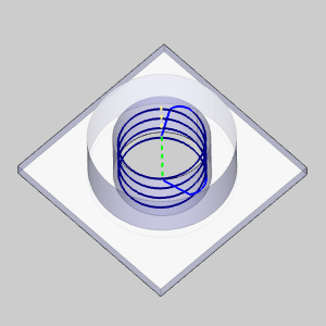
To create the toolpath, click Compute.
The result is shown next (the part is made transparent to make it easier to view the toolpath).
1 In
the CAM Tree,
right-click  Standard
Feature Mill Hole, and click Add
Toolpath Pattern.
Standard
Feature Mill Hole, and click Add
Toolpath Pattern.
2 In the Toolpath Pattern dialog box, click Rotate, and click Next>>.
3 In the Rotate group, set the Angle to 180, and set the Copies to 1.
4 Because the machining origin is placed at the center of the thread, which is also the center of rotation for the pattern, the Rotation Axis Origin values are X0 Y0.
5 To compute the toolpath pattern, click OK. The result is shown next.
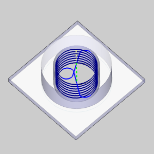
The multi-start thread is now complete.