Right-click  Emboss Model, and click Emboss from Component.
New to BobART is the ability to create Component/STL files from either a single emboss feature or an entire emboss model (To learn more, use the links at the end of this help topic.) The component is saved as an .stl file. These components can then be used to create one or more features using the Emboss from Component feature. Because the component is saved with the .stl extension, just about any .stl file can be used to create a component.
To create an Emboss from Component feature:
Right-click
Emboss Model, and click Emboss from Component.
In the Open dialog box, locate and select a component/.stl file, and click Open.
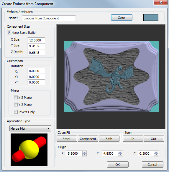
The Create Emboss from Component dialog box displays.
View the Create Emboss from Component dialog box
Emboss Attributes
Name - is the name of the feature that is displayed in BobART tree. You can type a new name or allow the system to automatically name and number each feature that is added. Note that you cannot use the hyphen (-) character with spaces around it, as this is reserved for the automatic naming and will be removed. You can however use it without spaces, for example, Emboss-Body).
Color - opens the Color dialog box. Select the desired color for the feature, and click OK. (The default color is set using the Solids color of the Settings Part/Settings Default dialog box.)
TIP: In the Create Emboss from Component dialog box, you can change the color to make it easier to view the component while you are modifying parameters. This can be helpful when multiple features share the same color.
Component Size
The Component Size group displays the current size of the component. You use the following parameters to adjust the size of the component.
Keep Same Ratio
 Select the check box to keep the same ratio between the X Size, Y Size,
and Z Depth. When you edit one of these parameters, the others are automatically
calculated to retain the original size ratio.
Select the check box to keep the same ratio between the X Size, Y Size,
and Z Depth. When you edit one of these parameters, the others are automatically
calculated to retain the original size ratio.
 Clear the check box to edit the X Size, Y Size, and Z Depth parameters
independently from each other. When you change one of these parameters,
the others are not changed.
Clear the check box to edit the X Size, Y Size, and Z Depth parameters
independently from each other. When you change one of these parameters,
the others are not changed.
Orientation
The Orientation group contains options to rotate and/or mirror the component as follows.
Rotation
The rotation parameters do not limit the angle of rotation in order to allow you all creative possibilities.
When rotating in X or Y, generally you should use values less than 90 degrees. For example, a 90 degree rotation may remove much of the detail of the component because embossed models cannot contain undercut areas. As another example, a rotation of greater than 90 degrees begins to appear as inverting the component. If you are not sure, experiment until you find the desired result.
X - is the amount of rotation around the X-axis.
Y - is the amount of rotation around the Y-axis.
Z - is the amount of rotation around the Z-axis.
Mirror
The Mirror parameters are used to mirror the component across one or more of three planes as described next. You can use any combination of the three mirror planes.
Select the check box to turn on the option.
Clear the check box to turn off the option.
X-Z Plane - mirrors the component (horizontally) across the XZ plane (or the X-axis).
Y-Z Plane - mirrors the component (vertically) across the YZ plane (or the Y-axis).
Invert Only - inverts the component across the XY plane. (Raised areas are lowered, and lowered areas are raised.)
Application Type
The Application Type defines how the feature is added to the model in reference to the other existing features. You can Add, Subtract, Merge High, or Merge Low. To learn more, view the Application Types help topic.
Zoom Fit
The Zoom Fit group is used to fit the view of the component, stock, or both in the preview window of the Create Emboss from Component dialog box.
Stock - fits the view of the stock to the preview window.
Component - fits the view of the component to the preview window.
Both - fits the view of both the stock and the component to the preview window.
Zoom
The Zoom group is used to zoom in or out based on the current Zoom Fit selection.
In - moves the view closer.
Out - moves the view further away.
Origin
The Origin group is used to move the location of the component in reference to the WCS or world coordinate system (X0Y0Z0). The origin of the component is always the lower-left corner of a bounding box drawn around the component. The bottom of the component is placed at Z0.
The XYZ values define the point/origin of the component from the WCS system (X0Y0Z0). You can type coordinate values, or you can also click the up or down arrows (called spin box controls) to increase or decrease the values. In addition to clicking the spin box arrows, you can click in each box (X, Y, or Z) and then scroll the middle mouse button up or down to change the value.
TIP: In the Emboss from Component dialog box preview, the component origin is always the lower-left corner. Even when the component is mirrored or rotated, the origin is updated to be the lower-left corner as shown in the following images.


OK - accepts any changes and closes the dialog box. (The first time you click OK, the feature is created and added to the BobART tree.)
Cancel - cancels the creation of the feature (the first time that the dialog box displays). When editing the feature, this cancels any changes and closes the dialog box.
After defining the parameters, you use the Emboss Features in the BobART Tree to finish creating, or edit, the feature.
When you finish defining the feature parameters and click OK, the feature is added to the BobART tree. You right-click each feature item in the tree to access a shortcut menu.
The Feature Shortcut Menus
 Emboss from Component
Right-click this item to access the following commands.
Edit - opens the Feature dialog box for you to modify the feature parameters.
Delete - removes the feature from the tree. Regenerate to view the change in the model.
Suppress/Unsuppress - is used to remove the feature from the model or to restore a suppressed feature. To update the model, Regenerate.
 Component
Right-click this item to access the following command.
Re/Load Model File - displays the Open dialog box for you to locate and select a component/.stl file. You can use this option to replace the current component for the feature. The new component is applied to the model when you regenerate.
After all necessary selections are made, you must regenerate to create the model.
To Regenerate the Model:
 Emboss Model, and click Regenerate.
TIP: Every time a change is made to an Emboss feature, you must Regenerate to update the model.