 Fillet Surfaces Fillet Surfaces
The Fillet Surfaces function is used to join two separate surfaces with a defined radius between them using one of five trimming options. To ensure tangency, this function trims surfaces, but it does not extend them.
To open the Fillet Surfaces function, do one of the following:
icon.
The parameters display in the  Data Entry tab of the Data-CAM Tree Manager.
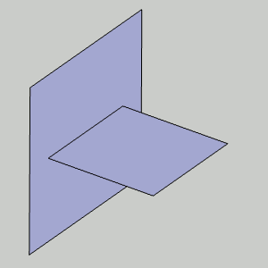
The boundary options determine how the fillet is trimmed at the outer boundaries. The following image shows the two original surfaces as a reference to the result shown below each option.

Blend - creates the fillet by trimming it and creating a tangent blend with the surface edges.

No Trim - creates the fillet between the two surfaces, but does not trim the outer edges of the fillet. The resulting fillet exceeds the larger surface by the radius amount.

Minimal - creates the fillet using the smaller surface.

Maximal - creates the fillet using the larger surface.

Bevel - create the fillet by trimming it and creating a beveled edge between the two surfaces.

![]() (Delete) - removes the First Surface/Solid
from the list.
(Delete) - removes the First Surface/Solid
from the list.
![]() (Delete) - removes the Second
Surface/Solid from the list.
(Delete) - removes the Second
Surface/Solid from the list.
1 Open the function and define all Data Entry parameters.
2 Click
to select the first of two surfaces.
3 Click
to select the second surface and create the previewed fillet.
4 Adjust
the Boundary Trim Type to preview the possible fillet results.
5 Click
OK to finalize the fillet.
The feature is added to the CAD Tree.
6 Repeat this process as needed.
7 To close the function, click Cancel.