Revolve Surface Revolve Surface
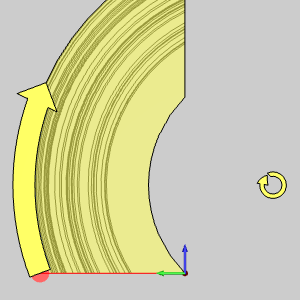
The Revolve function creates a revolved surface from a 2D geometry chain based on the settings that you define in the Data Entry tab. To perform the function, you chain select the curve to revolve, and confirm the selection to create the CAD preview. You then click OK to create the surface as shown in the CAD preview. When the CAD preview is turned off, the surface is created when you confirm the selection.

To open Revolve Surface, do one of the following:
In the Surfaces menu, click Revolve Surface.
On the Surfaces toolbar,
click the icon.
Right-click anywhere in the Workspace, point to CAD, Surfaces, and click Revolve Surface.
The parameters display in the  Data Entry tab
of the Data-CAM Tree Manager.
Data Entry tab
of the Data-CAM Tree Manager.
 Preview - Select the check box
to enable the CAD preview, which displays the result that will be
created when you click OK. You must select geometry and click
Preview - Select the check box
to enable the CAD preview, which displays the result that will be
created when you click OK. You must select geometry and click  OK to confirm the selection before the preview is created.
 Preview - Clear the check box
to turn off the CAD preview. The surface is created when you confirm the
selections.
Preview - Clear the check box
to turn off the CAD preview. The surface is created when you confirm the
selections.
|
|
|
|
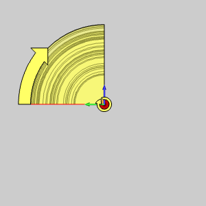
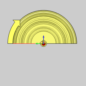
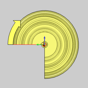
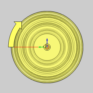
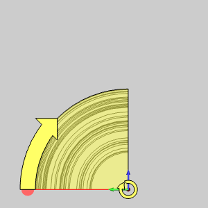
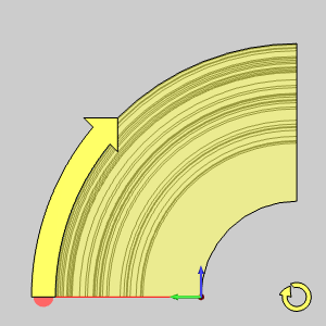
90° |
180° |
270° |
360° |
|
|
|
|
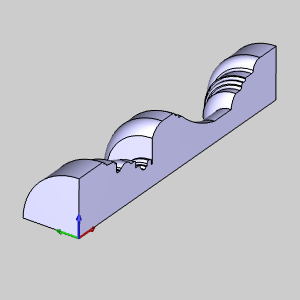
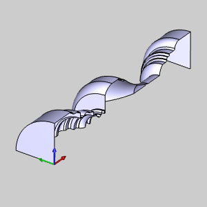
With Caps - creates surfaces on the top and bottom
of the extruded curve, thus making a solid.
With Caps - omits the top and bottom
surface of the extruded curve and creates a hollow shell.
|
|
|
|
Pick Axis - requires a line to be selected as
the axis around which the geometry is revolved.
Pick Axis - enables the Origin and
Direction parameters for you to type values to define the revolve axis.
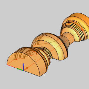
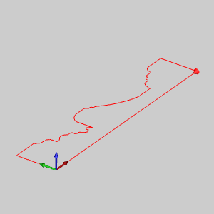
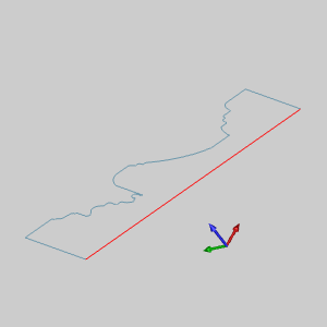
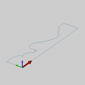
TIP: When the selected Revolve Curve is in line with the UCS, using Pick Axis is not necessary. When it is askew of the UCS Pick Axis makes its revolution simple. See the images below for a situational example of each.
|
|
|
|
Geometry |
X0, Y0, Z0 |
X0, Y-1, Z0 |
X0, Y-1, Z1 |
|
|
|
|
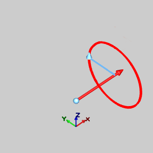
Direction X1, Y0, Z0 |
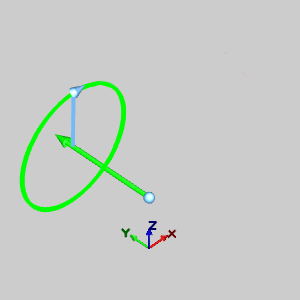
Direction X0, Y1, Z0 |
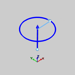
Direction X0, Y0, Z1 |
|
|
|
1 Open the function and define all Data Entry parameters.
2 Chain select the wireframe that you want to revolve:
A Click
near the end of the first chain entity to set the start of the chain.
B Hold Shift and click near the end of the last entity to set the end of the chain.
NOTE: If there is nothing in the chain you do not want to be selected, you can hold Shift and click near the end of the last entity to set the start and end of the chain in one click.
Once the chain is selected, the Preview appears.
This assumes that the default settings are sufficient to create a Revolve.
If they are not, a preview will appear once the parameters allow for the
creation of a Revolve.
3 Set
the axis of revolution using one of two methods:
A If
you are using Pick Axis, select a line to use as the axis of revolution.
The revolution axis can be selected as part of the revolve profile or not.
B If you are not using pick Axis, confirm that the proper Origin Point and Direction Point values are defined.
4 To create the surface, in the Data Entry Manager, click OK.
You can repeat this process for any other surfaces.
5 To close the function, click Cancel.
The feature is added to the CAD Tree.