Milling Spindle Zero
Degree Orientation (Z Axis)
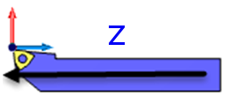
Tool Axial Direction = Z
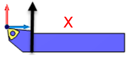
Tool Radial Direction = X
In this Topic Show
The Milling Spindle Configuration is used to define a milling spindle for multiaxis mill turn machines. This dialog box is accessed from the Machine Definition of the Current Settings.
To access the Milling Spindle Configuration from the Machine Definition, do one of the following:
The Milling Spindle Configuration displays.
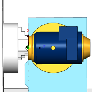
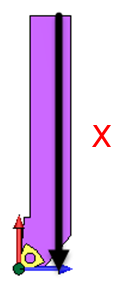
The following images show the two most common ways that a milling spindle is oriented when set to zero degrees on the physical machine. This orientation should be used when defining the parameters for the milling spindle as well as the tool direction parameters (as though a tool is mounted to the spindle in this orientation).
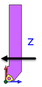
Milling Spindle Zero Degree Orientation (Z Axis) |
Tool Axial Direction = Z |
|
|
Tool Radial Direction = X |
|
|
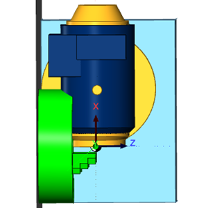
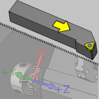
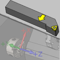
Milling Spindle Zero Degree Orientation (X Axis) |
Tool Axial Direction = X |
Tool Radial Direction = Z |
 |
 |
 |
The rotation axis of the milling spindle is set in reference to the machine zero coordinate system. (This defines the rotation axis of the spindle, not the tool.)
X - is selected when the rotation axis of the milling spindle is parallel to the X-axis of the machine.
Y - is selected when the rotation axis of the milling spindle is parallel to the Y-axis of the machine.
Z - is selected when the rotation axis of the milling spindle is parallel to the Z-axis of the machine.
User Defined - is selected when the rotation axis of the milling spindle is not parallel to the X, Y, or Z axes. Use this option to define a custom milling spindle rotation axis with the Direction and Base Point parameters.
Direction
The Direction group displays the direction vector of the selected Rotation Axis. When selecting X, Y, or Z, this in an informational display only. (For example, when set to Y, the vector displays as X0 Y1 Z0.) When selecting User Defined, you can type the XYZ values to determine the custom direction vector.
Base Point
This parameter determines the distance from the machine zero location or the front face of the milling spindle, to the milling spindle rotation axis. (The face of the milling spindle is aligned to machine zero location when creating the geometry files).
X - is the distance from the machine zero to the milling spindle rotation axis along the X-axis.
Y - is the distance from the machine zero to the milling spindle rotation axis along the Y-axis.
Z - is the distance from the machine zero to the milling spindle rotation axis along the Z-axis.
These parameters determine the limits of the milling spindle rotation axis (indexing angles).
Min - is the minimum rotation angle (in degrees) allowed for indexing the milling spindle.
Max - is the maximum rotation angle (in degrees) allowed for indexing the milling spindle.
Initial - is the rotation angle (in degrees) of the milling spindle in its initial position. Note that this value is used in simulation to position the head during tool changes.
This parameter defines the direction for positive rotation of the milling spindle. This can be set to either CW (clockwise), or CCW (counterclockwise). (Note that changing from CCW to CW automatically adjusts the Rotation Axis Direction (XYZ) vectors to negative.)
The tool direction parameters are used for both milling tools and lathe tools that may be attached to the milling spindle. You can use the diagram at the beginning of this document to guide you.
The tool axial direction parameter matches the rotation axis of the tool to one of the axes of the machine zero coordinate system. These values are set based on the tool orientation with the milling spindle set to zero degrees as shown in the beginning of this topic.
X - is selected when the axial direction of the tool is parallel to the X-axis of the machine.
Y - is selected when the axial direction of the tool is parallel to the Y-axis of the machine.
Z - is selected when the axial direction of the tool is parallel to the Z-axis of the machine.
User Defined - is selected when the axial direction of the tool is not parallel to the X, Y, or Z axes. Use this option to define a custom axial direction with the Direction parameter.
Direction
The Direction group displays the direction vector of the selected Axial Direction. When selecting X, Y, or Z, this in an informational display only. (For example, when set to Y, the vector displays as X0 Y1 Z0.) When selecting User Defined, you can type the XYZ values to determine the custom direction vector.
The tool radial direction parameter matches the radial direction of the tool (perpendicular to the tool's rotation axis) to one of the axes of the machine zero coordinate system. These values are set based on the tool orientation with the milling spindle set to zero degrees as shown in the beginning of this topic.
X - is selected when the axial direction of the tool is parallel to the X-axis of the machine.
Y - is selected when the axial direction of the tool is parallel to the Y-axis of the machine.
Z - is selected when the axial direction of the tool is parallel to the Z-axis of the machine.
User Defined - is selected when the radial direction of the tool is not parallel to the X, Y, or Z axes. Use this option to define a custom axial direction with the Direction parameter.
Direction
The Direction group displays the direction vector of the selected Radial Direction. When selecting X, Y, or Z, this in an informational display only. (For example, when set to Y, the vector displays as X0 Y1 Z0.) When selecting User Defined, you can type the XYZ values to determine the custom direction vector.
The Number of Stations should be set to match the number of available stations in the tool changer for the milling spindle. This determines how many stations can be added to the milling spindle in the Mill Turn Tool Crib.
This button displays the Open dialog box for you to locate and select a .stl file that represents the milling spindle. Be sure to select the appropriate STL File Unit of Inch or Metric first, based on the unit type in which the model was created. The model is used in machine simulation, so make the model as basic or as detailed as you want to see in machine simulation.
IMPORTANT: Be sure to orient the .stl file with it aligned to the machine zero, or the coordinate system used to align the machine geometry files, the same way that it is on the physical machine with the spindle rotation axis at zero degrees.