Toolpath Backplot Mode (B)
- simulates the toolpath only without material removal (the stock
button becomes unavailable as well as many of the material removal verification
tools).
Toolpath Backplot Mode (B)
- simulates the toolpath only without material removal (the stock
button becomes unavailable as well as many of the material removal verification
tools).In this Topic Show
The Simulation tab contains many of the most used buttons for controlling the simulation. This tab contains the Simulation, Control, Simulation Run Speed, Views, Visibility, and Toolpath Rendering groups. The available buttons for each group are explained next.
The Simulation group of the Simulation tab contains buttons that allow you to select the modes for simulation as follows. When hovering over some of these options, you will notice a letter in parentheses. This letter is the available shortcut key to access this item without needing to click on it directly.
The simulation can be run in one of two modes for material removal or toolpath backplot only.
Toolpath Backplot Mode (B)
- simulates the toolpath only without material removal (the stock
button becomes unavailable as well as many of the material removal verification
tools).
 Material Removal Mode (V)
- simulates the toolpath including material removal. Many of the features
of the simulation are designed to work with this mode to verify the material
removal.
Material Removal Mode (V)
- simulates the toolpath including material removal. Many of the features
of the simulation are designed to work with this mode to verify the material
removal.
The simulation display mode is controlled using one of the following options.
 Time-based Mode - the machining
simulation displays with real time feedrate motions. Machine motions are
very fluent, machining time is exact.
Time-based Mode - the machining
simulation displays with real time feedrate motions. Machine motions are
very fluent, machining time is exact.
 NC-based Mode - the machining
simulation only uses the tool positions from the move list. Machine motions
jump from one position to the next.
NC-based Mode - the machining
simulation only uses the tool positions from the move list. Machine motions
jump from one position to the next.
 Length-based Mode - the machining
simulation uses a constant speed, distance/time regardless of the feed
rate.
Length-based Mode - the machining
simulation uses a constant speed, distance/time regardless of the feed
rate.
The simulation focus determines how the tool, machine, and material/workpiece display using one of the following options.
 Tool Focus (T)
- simulates the program with the tool and workpiece visible, with
the tool remaining stationary.
Tool Focus (T)
- simulates the program with the tool and workpiece visible, with
the tool remaining stationary.
 Workpiece Focus (W) - simulates
the program with the tool and workpiece visible, with the workpiece remaining
stationary.
Workpiece Focus (W) - simulates
the program with the tool and workpiece visible, with the workpiece remaining
stationary.
 Machine Focus (M)
- simulates the program showing the kinematic motion of all machine
elements.
Machine Focus (M)
- simulates the program showing the kinematic motion of all machine
elements.
The Control group on the Simulation tab contains buttons for controlling the playback of the simulation.
 Run (R) - plays the simulation.
You can click the down arrow under this button to select the Loop playback
button.
Run (R) - plays the simulation.
You can click the down arrow under this button to select the Loop playback
button.
 Loop (L) - sets the simulation
to run repeatedly, or loops back to the beginning of the simulation when
the end is reached.
Loop (L) - sets the simulation
to run repeatedly, or loops back to the beginning of the simulation when
the end is reached.
 Stop (S) - stops the simulation
at the current position and retracts the tool for you to view the cut
stock material.
Stop (S) - stops the simulation
at the current position and retracts the tool for you to view the cut
stock material.
 Pause (P) - stops
the simulation at the current position without retracting the tool.
Pause (P) - stops
the simulation at the current position without retracting the tool.
 Fast Forward
(Space) - advances the simulation to the last step without showing
the simulation process in the simulation window. If a collision happens
during fast run, it is reported.
Fast Forward
(Space) - advances the simulation to the last step without showing
the simulation process in the simulation window. If a collision happens
during fast run, it is reported.
 Step Forward (Page Down) - allows
you to incrementally move through the simulation by moving the simulation
to the next toolpath point/segment.
Step Forward (Page Down) - allows
you to incrementally move through the simulation by moving the simulation
to the next toolpath point/segment.
 Step Backward
(Page Up) - allows you to incrementally move through the simulation
by moving the simulation to the next toolpath point/segment.
Step Backward
(Page Up) - allows you to incrementally move through the simulation
by moving the simulation to the next toolpath point/segment.
 Next Operation (Enter) -
advances the simulation to the next operation (automatically simulating
the previous operation).
Next Operation (Enter) -
advances the simulation to the next operation (automatically simulating
the previous operation).
 Previous Operation (Backspace)
- returns the simulation to the previous operation.
Previous Operation (Backspace)
- returns the simulation to the previous operation.
 Restart (Home) - starts machining
over again from the beginning and resets the material removal (Material
Removal mode).
Restart (Home) - starts machining
over again from the beginning and resets the material removal (Material
Removal mode).
The speed slider allows you to control the speed of playback in simulation.
 Simulation Speed (-/=) - allows
you to run the simulation faster or slower. To decrease the simulation
speed move the slider to the left. To increase the simulation speed, move
the slider to the right.
Simulation Speed (-/=) - allows
you to run the simulation faster or slower. To decrease the simulation
speed move the slider to the left. To increase the simulation speed, move
the slider to the right.
The view presets allow you to change the viewing orientation of the elements in the simulation window.
 Fit (F) - makes all elements on
the screen fit to the available window size.
Fit (F) - makes all elements on
the screen fit to the available window size.
 Isometric (Ctrl - 7) - sets the
isometric view.
Isometric (Ctrl - 7) - sets the
isometric view.
 Top (Ctrl - 5) - sets the top
view.
Top (Ctrl - 5) - sets the top
view.
 Front (Ctrl - 1) - sets the front
view.
Front (Ctrl - 1) - sets the front
view.
 Right (Ctrl - 4) - sets the right
view.
Right (Ctrl - 4) - sets the right
view.
 Bottom (Ctrl - 6) - sets the bottom
view.
Bottom (Ctrl - 6) - sets the bottom
view.
 Left (Ctrl - 3) - sets the left
view.
Left (Ctrl - 3) - sets the left
view.
 Back (Ctrl - 2) - sets the back
view.
Back (Ctrl - 2) - sets the back
view.
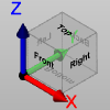
The Smart View feature can be used by a simple click on each of the faces of the cube which is available in the graphical area. On the cube faces there are written the names of the views Top, Bottom, Right, Left, Front, and Back. Click here to see an example.
The viewing orientation of the elements in the simulation window can be controlled using the mouse as follows.
To pan the view, or shift the objects in the simulation window two-dimensionally, press and hold the right mouse button while dragging around the screen.
To zoom in or out, or move the objects in the simulation window closer or further away, roll the middle mouse button forward or backward.
To rotate the viewing orientation of objects in the simulation window, click and drag the left mouse button. Note that rotation occurs around the location that you click.
To access the right-click menu, double right-click in the simulation window. If you double right-click on an object, the object will highlight and you will see options to show, make transparent, or hide. If you right-click on a tool there will also be other options to control the view of the holder, arbor, shaft and flute individually.
The visibility group of the Simulation tab provides options for you to change the visibility status of various items in the simulation window. Most of these buttons are three stage: show, transparent, or hide. Each time you click a button, it changes to the next option. You can also click the down arrow that displays under the button to select the exact status you want from a list.
 Toolpath
 Tool
Tool
 Workpiece
 Stock
Stock
 Initial Stock
 Machine Housing
The Toolpath Rendering group provides control over how the toolpath displays in the simulation window. Note that all of these options become unavailable when the toolpath visibility is set to hide.
 Tool Center - the toolpath displays
at the tool center.
Tool Center - the toolpath displays
at the tool center.
 Tool Tip - the toolpath displays
at the tool tip position.
Tool Tip - the toolpath displays
at the tool tip position.
 All Operations - shows the toolpath
for all operations.
All Operations - shows the toolpath
for all operations.
 Current Operation - shows the
toolpath for the current operation only.
Current Operation - shows the
toolpath for the current operation only.
 Follow - shows only the machined
toolpath.
Follow - shows only the machined
toolpath.
 Trace - shows only the remaining
toolpath.
Trace - shows only the remaining
toolpath.
 Segment - highlights the current
toolpath segment during each tool movement.
Segment - highlights the current
toolpath segment during each tool movement.
 Tool Vector - shows the tool-axis
vectors at each toolpath point.
Tool Vector - shows the tool-axis
vectors at each toolpath point.
 Toolpath Points - indicates each
toolpath segment with start and end points.
Toolpath Points - indicates each
toolpath segment with start and end points.
 Leads - shows or hides the lead-in
and lead-out of the toolpath.
Leads - shows or hides the lead-in
and lead-out of the toolpath.
 Links - shows or hides the linking
portions of the toolpath.
Links - shows or hides the linking
portions of the toolpath.