Open a new graphics area. To do this, left click on the File menu at the top of the screen and then left click on New.
Click on the Line Coordinates icon on the CAD toolbar or choose the Coordinates function from the Lines menu.
The Data-CAM Tree Manager will now be populated with fields for user input.
Input -3.0 for Start X, 1.0 for the Start Y, 0.0 for the Start Z and -1.0 for End X, 1.0 End Y and 0.0 in End Z.
Click on OK in the Data-CAM Tree Manager and a line will be drawn in the graphics area.
Input 1.0 for Start X, -1.0 for the Start Y, 0.0 for the Start Z and 3.0 for End X, -1.0 End Y and 0.0 in End Z.
Click on OK in the Data-CAM Tree Manager and another line will be drawn in the graphics area.
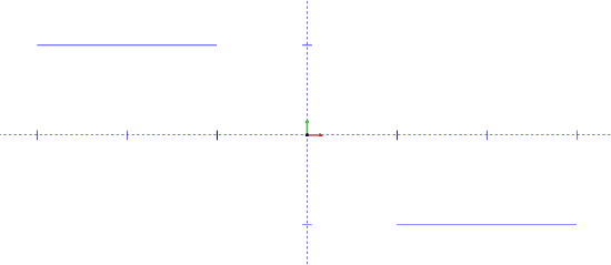
The drawing should look like this:

Click on the Spline Blended icon on the CAD toolbar or choose the Blended function from the Splines menu.
Hover the cursor over the far right end of the left-side line first. Click once with the left mouse button and a small point will appear at the end of the line.
The preview will show the current blending spline wherever the mouse is moved.
Hover the cursor over the far left end of the right-side line. Click once with the left mouse button and a small point will appear at the end of the line.
To set the spline into its location, right click anywhere in the graphics area and click OK.
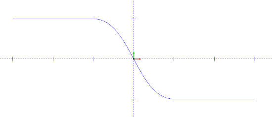
The spline will be drawn as illustrated here:

To end this function, right click anywhere in the graphics area and choose Cancel from the menu that will appear, or click on Cancel in the Data-CAM Tree Manager.
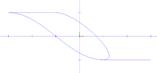
TIP: The Blended function can be used to smoothly join any number of snap points in the drawing. Here is an illustration of the same two lines, but the with the spline joined again back to the beginning of the first line:

Note that the spline always attempts to come tangent with each entity chosen as a snap point.