Create Geometric Contours
Example
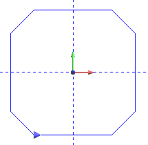
The following steps can be applied to any wireframe chains to create
a contour entity with a defined direction that can be used for machining
features. You can open an existing file or draw any rectangle (as explained
in Create a Rectangle) to use with the following steps.
- In the Other menu, click
Contour.
- The Contour parameters are displayed in the Data Entry tab.
- In the Direction group,
select CW to create the contour
with clockwise direction, or select CCW
to create a contour with a counter-clockwise direction.
- Under Chain Beginning,
you can select Set Longest as Start.
This setting automatically places the start point of the contour on
the longest entity of the selected chain.
- You can use Selected Start Point/Automatic
to set the start point of the contour based on your selection method.
- If you window pick the entities (click and drag a window),
the software automatically sets the start point of the contour.
- If you select each entity one at a time, the start point of
the contour is placed on the first selected entity.
- If you chain select the entities (press and hold Shift, then
click), the closest end point of the entity that you click is
set as the end of the chain. (Be aware that the direction affects
the start location when using chain selection for closed contours.)
When chain-selecting open chains to create a contour, the direction
is defined only by your selection. None of the Data Entry parameters
apply to open contours when using chain selection.
TIP: The start
of a contour can't be placed in the middle of a single entity. For example,
if you have a line (a single entity) and you want the start point to be
in the middle of that line, you must first break the line at that point.
- Select the entities in the Workspace using one of the methods explained
in Step 5.
- To confirm the selection, right-click anywhere in the Workspace,
and click
 OK.
OK.
- The entities are grouped to create the contour, and the direction
of the contour is displayed on the entities in the Workspace. The
contour can now be selected as a single entity. When you create a
machining feature with the contour, the direction of the feature is
controlled by the contour direction. (You can also use the Start Point
of the feature to control the direction of a feature without the need
to create a contour.)
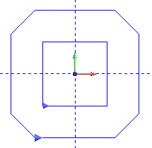
The following image shows two groups of
entities that are selected at the same time. The result is two separate
contours, one for each chain. This is done using the same steps as explained
earlier. Note that when you create more than one contour at a time, the
same direction is used for all contours.
TIP: To
delete a contour, enable selection mode (in the Edit menu, click Select
Mode), click to select the contour, and press Delete. The original entities
are not affected (the contour is reverted back to the original group of
entities). Be aware that if you use Translate to move a contour entity,
the original entities do not move with the contour (they remain at their
original location).
Related Topics
Contours
The
CAD_Tutorials
Setting
Chain Start Points for Operations