At this point you could Cancel the function because the gear is finished. Before doing so, let's create another gear using the Pick method instead of the Enter method.
In the Data Entry tab, change the Number of Teeth to 15.
Change the Pressure Angle to 25.00.
Change the Outside Diameter to 4.00.
Change the Root Diameter to 2.00.
Change the Pitch to 2.50. (Notice the order of the values entered. This was done to avoid an error message while entering values. If we entered the Pitch first, we would have received the error message. The software checks the values to make sure that they are correct. If you receive the error message before entering all values, click OK and continue entering the values. If you receive the error message on the last value that you enter, you may need to confirm that you are using proper values for the gear.)
In the Origin group, click Pick. This means that you pick the origin location of the gear in the graphics area. This can be an arbitrary location or you can use the snap point of another entity to set the origin of the gear.
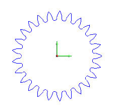
Point to any location in the graphics area and click to create the Gear. Each time that you click, a new gear is created. (You can also point to any entity, and click to place the origin of the new gear at the nearest snap point of the entity.)
To end the function, click Cancel.
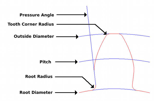
TIP: The following diagram provides an illustration of all the Gear parameters (except Number of Teeth).
|
 |