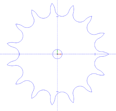
Input 15 for the Number of Teeth, 0.5 for the Pitch, 0.375 for Roller Diameter, and 0.25 for the Bore Diameter.
In the Origin field, left click on Enter and input 0.0 for X, Y, and Z.
Then, click OK
to create the sprocket.
To end the function, click Cancel in the Data-CAM Tree Manager or right click anywhere in the graphics area and choose Cancel in the pop-up menu.
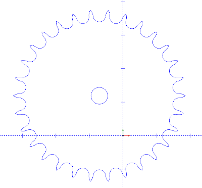
Input 30 for the Number of Teeth, 0.5 for the Pitch, .375 for Roller Diameter, and .5 for the Bore Diameter.
Click on Pick in the Origin field and the X, Y, and Z coordinate boxes will be grayed out. Click OK.
Move the cursor into the graphics area and left click on any location to create the gear.
To end the function, click Cancel in the Data-CAM Tree Manager or right click anywhere in the graphics area and choose Cancel in the pop-up menu.
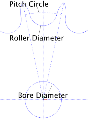
TIP: The following diagram displays the data you would use in the Sprocket dialog and the feature of the sprocket that they pertain to: