The Point Arc Center function is used to create a point at the center of an arc or circle. This function automatically creates the point in the plane of the arc regardless of its position in the graphics area (the arc does not have to be flat to the active UCS or user coordinate system). To perform the function, you click the arc, and the point is created without the need to confirm the selection.
1 In the File menu, click New.
2 In the Arcs menu, click Coordinates.
The Arc Coordinate parameters display in
the ![]() Data Entry tab of the
Data CAM Tree Manager.
Data Entry tab of the
Data CAM Tree Manager.
3 In the Data Entry tab, double-click in the Center X box to select all of the text (if it is not already selected).
Type 0.500, and press Tab to move to the next box.
In the Center Y box, type 0.500, and press Tab twice.
In the Radius box, type 0.250, and press Tab to update the CAD preview.
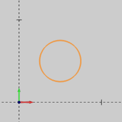 |
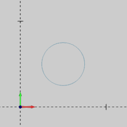
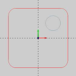
To create the arc as shown in the CAD preview, click OK.
 |
4 In the Other menu, click Rectangle.
Under Corner Type, click Radius.
To create the rectangle as shown in the CAD preview, click OK.
 |
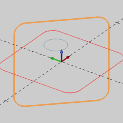
5 In the Utilities menu, click Rotate.
In the Angle Around Axis group, change the X value to 90.00.
Press Tab twice, and in the Z box, type -45.00.
Click Copy. (Use the default value of 1.)
In the Origin group, click Enter.
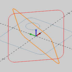
6 Press and hold Shift, and in the graphics area, click to chain select the rectangle.
To confirm the selection, press the Spacebar. [Alternatively, you can
right-click anywhere in the graphics area, and click OK. You can also
click  (OK) on the Miscellaneous
toolbar. Any of these methods can be used to confirm selections.]
(OK) on the Miscellaneous
toolbar. Any of these methods can be used to confirm selections.]
The CAD preview in the graphics area updates. Press Ctrl+7 to select the ISO 2 view. (Alternatively, in the View menu, point to Views, and click ISO 2.)
 |
To create the rotated copy of the rectangle, click OK.
 |
NOTE: When you click OK to create the rotated rectangle, the newly created rectangle becomes the current selection, and the CAD preview shows the next entity that would be created if you performed the function again.
7 To end the function, click Cancel.
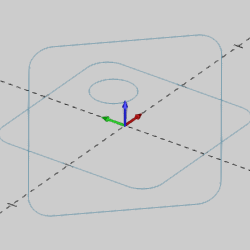 |
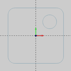
1 In the Points menu, click Arc Center.
2 In the graphics area, point to the circle so that it displays in the Highlight color.
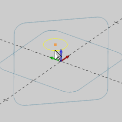 |
Notice that the CAD preview displays a point at the center of the circle.
Click to select the arc and create the point.
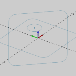 |
NOTE: There is no need to confirm geometry selection when using Point Arc Center. The point is automatically created when you select an arc.
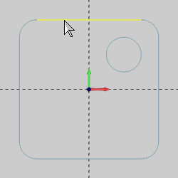
3 Click to select one of the arcs of the rectangle drawn in the Top X/Y plane.
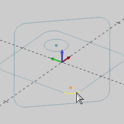
The point is automatically created in the same plane as the arc. The Point Arc Center function automatically creates points in the plane of the arc (the arc does not have to be flat to the active UCS).
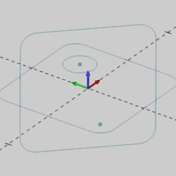
4 Click to select one of the arcs of the rectangle that was rotated.
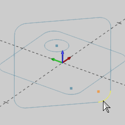
The point is automatically created in the proper plane.
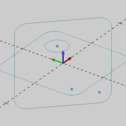
Rotate the view to confirm that the points are created in the same plane as the selected arc.
5 To end the function, click Cancel.
This concludes the example.