Open a new graphics area by left clicking on the File menu and then on New.
Click on View in the main menu, hover the cursor over Views and choose the ISO1 option to place the view in a 3 dimensional mode.
Click on the Cube icon on the Solids toolbar or select the Cube function from the Solids menu.
The Data-CAM Tree Manager will be populated with fields for user input.
The prompt line will read: "Enter Values in the Data-CAM Tree Manager, then Left click the OK Button.
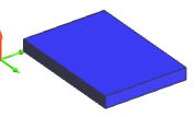
Input 1.25 for the Length, 0.875 for the Width, and 0.125 for the Height.
In the Origin field, left click on Enter and select Bottom Left from the drop-down box.
Input 0.0 for X, 0.25 for Y, and 0.0 for Z.
Click OK to create the cube.
To end this function, click Cancel in the Data-CAM Tree Manager or right click anywhere in the graphics area and choose Cancel from the menu that will appear.
Open a new graphics area by left clicking on the File menu and then on New.
Click on View in the main menu, hover the cursor over Views and choose the ISO1 option to place the view in a 3 dimensional mode.
Click on the Cube icon on the Solids toolbar or select the Cube function from the Solids menu.
The Data-CAM Tree Manager will be populated with fields for user input.
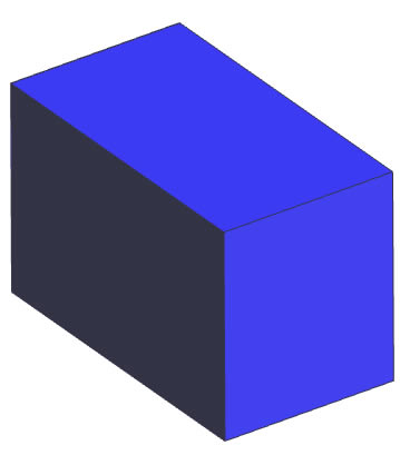
Input 3.2 for the Length, 1.8 for the Width, and 2.1 for the Height.
In the Origin field, click on Pick and choose Center from the drop-down box.
Place the cursor anywhere in the graphics area and click to create the cube.
To end this function, click Cancel in the Data-CAM Tree Manager or right click anywhere in the graphics area and choose Cancel from the menu that will appear.