The Cube parameters display in the Data Entry tab of the Data-CAM Tree Manager.
The Preview appears.
In this Topic Show
In this example, you will create geometry and then learn how to use the Offset Surface function on that geometry. This example will have you:
Create a Cube
Unstitch the Cube
NOTE: In the images below, both the Show Axis X-Y and Show Gnomon toggles have been disabled in the Axis X-Y group of the Settings Part > Display dialog.
1 In
the File menu, click New.
A New window opens.
2 Enter
into an ISO 2 view by pressing
Ctrl+7.
3 Open
![]() Cube by
selecting the function from Solids
menu.
Cube by
selecting the function from Solids
menu.
The Cube parameters display in the Data Entry tab of the Data-CAM Tree
Manager.
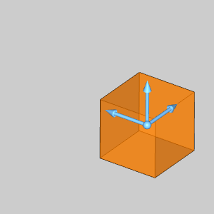
The Preview appears.
4 The
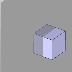
cube being created will be left at the default size, and location.
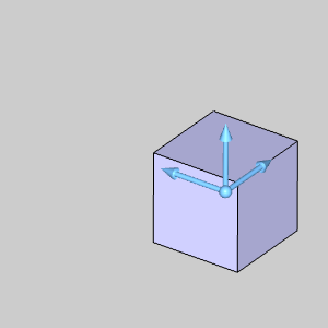
Click OK to confirm the cube.
The Cube is created in the graphics area and a ![]() Cube feature is created in the
Cube feature is created in the ![]() CAD Tree.
CAD Tree.
1 In
the Utilities menu, hover over
Stitching, and select Unstitch
Surface from Solid.
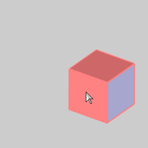
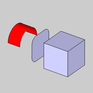
1 Hover over the surface as
seen in the image below.
The surface highlights.
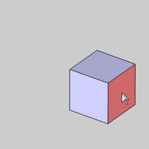
2 Click
the surface.
The surface is no longer highlighted until the mouse is moved again.
No change is visible, but the surface is unstitched from the cube and an
![]() Unstictch
Surface from Solid feature is created in the
Unstictch
Surface from Solid feature is created in the ![]() CAD Tree.
CAD Tree.
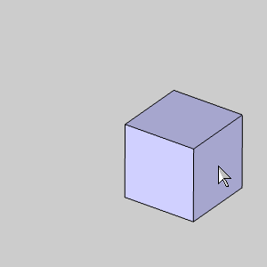
3 Click
Cancel to exit the function.
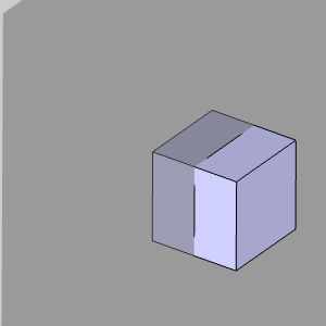
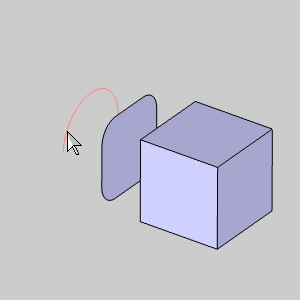
4 Hover
of a different surface of the cube as seen in the image below.
Notice the surface has been unstitched from the cube.
1 In
the ![]() UCS
tab of the Layer-UCS-Post Manager,
right-click
UCS
tab of the Layer-UCS-Post Manager,
right-click ![]() Front
(X/Z) and select Active UCS
in order to create another surface on the Front Plane.
Front
(X/Z) and select Active UCS
in order to create another surface on the Front Plane.
The Front Plane highlights.
1 Open
the ![]() Rectangular
Plane function by clicking on that option in the Surfaces
menu.
Rectangular
Plane function by clicking on that option in the Surfaces
menu.
The Rectangular Plane dialog opens in the Data Entry tab of the Data-CAM
Tree Manager.
2 In
the Origin group, select Enter.
The Preview appears inside the cube at X0, Y0, Z0.
3 In
the Origin group, change the Z
value to -2.0000.
The Preview updates.
4 Click
OK to confirm placement of the
Rectangular Plane.
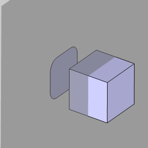
The surface is created in the graphics area and a ![]() Rectangular Plane feature is added
to the
Rectangular Plane feature is added
to the ![]() CAD
Tree.
CAD
Tree.
1 Open
the ![]() Arc Coordinate
function by clicking on
Arc Coordinate
function by clicking on ![]() Coordinates in the Arcs
menu.
Coordinates in the Arcs
menu.
The Arc Coordinate dialog opens in the Data Entry tab of the Data-CAM Tree
Manager and the Preview displays.
2 Update
the values in the Arc Coordinate dialog to match the following:
Center X Center Y Center Z Radius Start Angle End Angle |
= 0.0000
= 0.0000 = -3.0000 = 1.0000 = 0.0000 = 180.0000 |
The
Preview updates.
3 Click
OK to confirm the placement of
the arc.

1 In
the ![]() UCS
tab of the Layer-UCS-Post Manager,
right-click
UCS
tab of the Layer-UCS-Post Manager,
right-click ![]() Top
(X/Y) and select Active UCS
Top
(X/Y) and select Active UCS
The Front Plane disappears.
1 Open
the ![]() Extrude
Curve function by clicking on that option in the Surfaces
menu.
Extrude
Curve function by clicking on that option in the Surfaces
menu.
The Extrude Curve dialog opens in the Data Entry tab of the Data-CAM Tree
Manager.
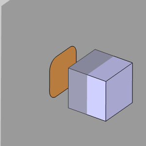
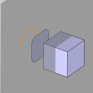
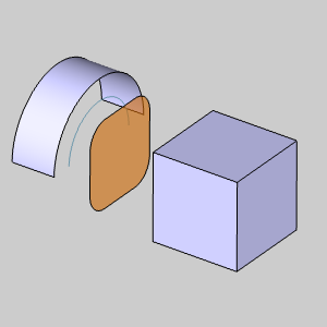
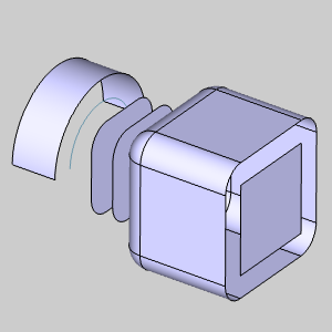
2 Hover
over the arc as seen in the image below.
3 Click
the arc.
The Preview appears.
4 In
the Positive Direction group,
change the Distance value to 0.0000.
The Distance in the Other Direction group automatically becomes 1.0000,
and the Preview updates.
5 Click
OK to create the Extrude Curve.
The Extrude Curve is created in the graphics area and an ![]() Extrude
Curve feature is added to the
Extrude
Curve feature is added to the ![]() CAD
Tree.
CAD
Tree.
1 Open
the  Offset
function by clicking on that option in the Surfaces
menu.
Offset
function by clicking on that option in the Surfaces
menu.
The Offset Surface dialog opens in the Data Entry tab of the Data-CAM Tree
Manager.
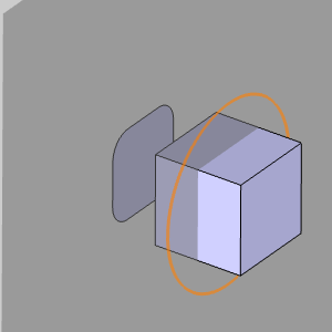
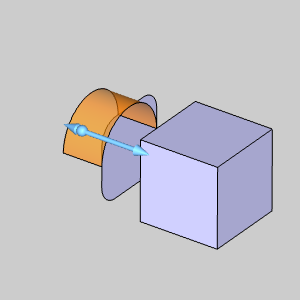
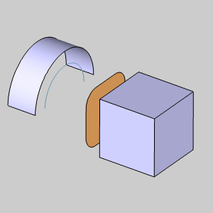
2 Hover
over the extruded arc as seen in the image below.
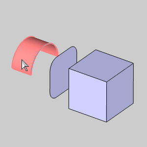
3 Click
the surface.
The surface is selected and is added to the Selected Geometry list.
4 In
the Parameters group, change the
Distance to 0.5000.
5 Next
to Options, click  to access the options.
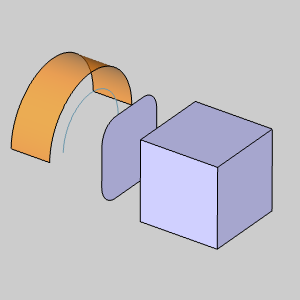
6 Clear
the check box for Keep Original.
The offset we create will now replace the original surface.
7 Click
Show Preview.
The Preview appears.
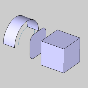
8 Click
OK to confirm the surface.
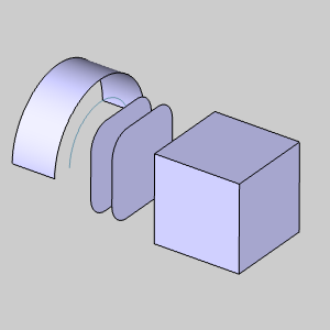
The offset is created in the graphics area and an
Offset Surface feature is created
in the ![]() CAD
Tree.
CAD
Tree.
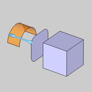
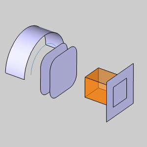
1 Hover
over the rectangular plane as seen in the image below.
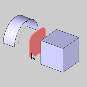
2 Click
the rectangular plane.
The rectangular plane is added to the Selected Geometry list.
With the Show Preview button still selected, the Preview automatically
appears.
3 In
the Parameters group, change the
Distance value to -0.5000.
The Preview updates.
4 In
the Options group, select the
check box for Keep Original.
The offset we create will now be in addition to the original surface.
5 Click
OK to confirm.
The offset is created in the graphics area and an
Offset Surface feature is created
in the ![]() CAD
Tree.
CAD
Tree.
1 In
the Options group, clear the check
box for Fillet Edges.
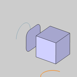
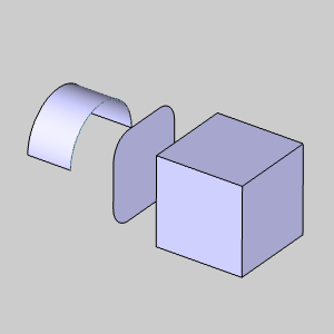
2 Hover
over the cube as seen in the image below.
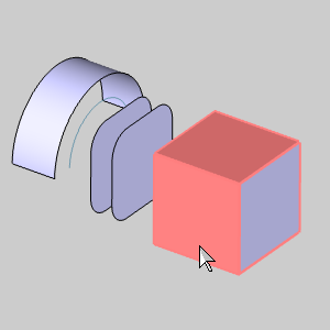
3 Click
the cube.
The cube is selected and added to the Selected Geometry list.
The Preview appears.
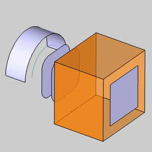
4 In
the Parameters group, change the
Distance value to 0.5000.
The Preview updates.
5 In
the Options group, select the
check box for Fillet Edges.
The Preview updates.
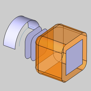
6 Click
OK to confirm.
The offset is created in the graphics area and another
Offset Surface feature is created
in the ![]() CAD
Tree.
CAD
Tree.
7 To
end this function, click Cancel.
This concludes the example.