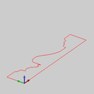
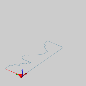
The file opens.
Leave the file in the ISO 2 view.
This example will demonstrate how to use the Revolve Surface function.
NOTE: In the images below, the Show Axis X-Y toggle has been disabled in the Axis X-Y group of the Settings Part > Display dialog. The Gnomon has been used to show the axes of rotation.
1 In
the File menu, click Open.
2 In the Open dialog box, navigate to C:\BobCAD-CAM Data\BobCAD-CAM V**\Examples.
NOTE: This is the default install location. If you performed a custom install, navigate to the location in which you installed the software.
3 Select
revolved surface example.bbcd,
and click Open.
The file opens.
Leave the file in the ISO 2 view.
4 Open
 Revolve
by selecting the function from Surfaces
menu.
Revolve
by selecting the function from Surfaces
menu.
The Revolve Surface parameters display in the Data Entry tab of the Data-CAM
Tree Manager.
5 Deselect
the Preview check box.
NOTE: This step is not necessary to the creation of a Revolve and is used in this example only to allow us to see the result of the chain selection easier.
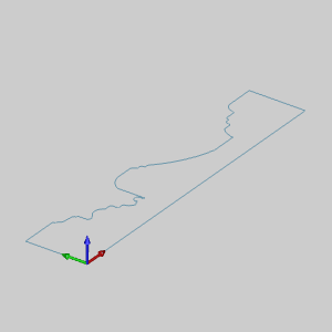
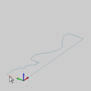
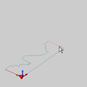
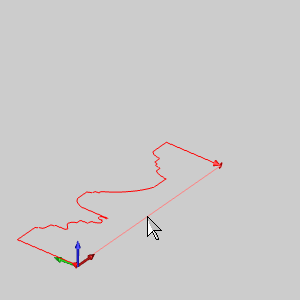
6 In
the graphics area, hover over the entity shown below, and press and hold
Shift, before clicking the entity
to chain-select the entire chain.
NOTE: Notice that the direction arrow is now displayed on the geometry. When you chain select an entity for functions that have a direction, the nearest snap point of the entity that you select is defined as the end of the chain. Alternatively, you can click an entity to define the start of the chain, and then hold Shift and click the end of another entity to define the end of the chain. The steps in this example eliminate the extra selection. When you are selecting a closed chain to revolve, the start and end location of the chain are not important.
7 Select
the Preview check box.
The Preview displays.
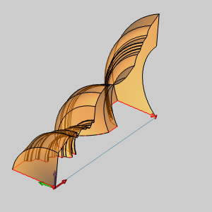
8 In
the Rotation Angle box, enter
a value of 90.00 and press Tab.
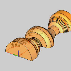
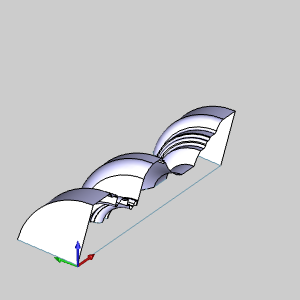
The Preview Updates
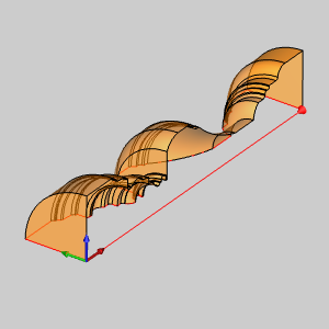
9 Select
the With Caps check box.
The Preview updates to show the Revolve Surface being created as solid
instead of a single revolved surface.
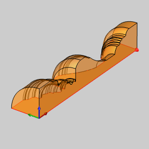
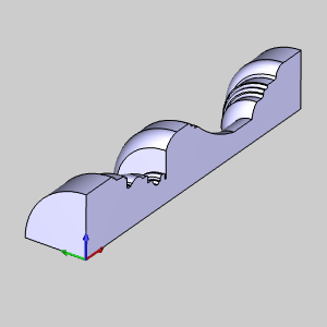
10 To
create the geometry as shown in the CAD preview, in the Data Entry tab,
click OK. The profile is revolved
90 degrees around the X-axis and a
Revolve feature is created in
the![]() CAD Tree.
CAD Tree.
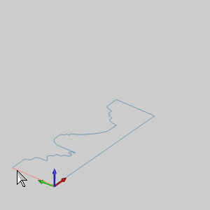
11 To end the function, click Cancel.
This concludes Example 1. Leave the file open and continue to Example 2 to learn more about Revolve Surface.
1 After
completing Example 1, press Ctrl+Z
to undo the last revolve. Or, in the Edit menu, click Undo.
2 Open
 Rotate by
selecting the function from Utilities
menu.
Rotate by
selecting the function from Utilities
menu.
The Rotate parameters display in the Data Entry tab of the Data-CAM Tree
Manager.
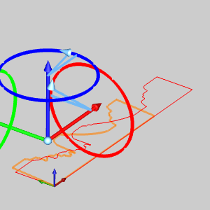
3 Hover
over the an entity in the chain, then hold Shift
and click that entity to chain select the entire chain.
4 Right-click
and select  OK
to confirm the geometry to be rotated.
OK
to confirm the geometry to be rotated.
5 For
the Angle Around Axis group, enter:
For the Origin group, enter:
The Preview updates for each entry. With
the values entered, the preview should match the one seen in the image
below.
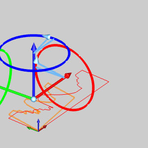
6 Click
OK to finalize the rotation.
The Preview updates to show the results should the current values be applied
again.
7 Open
Revolve
by selecting the function from Surfaces
menu.
The Revolve Surface parameters display in the Data Entry tab of the Data-CAM
Tree Manager.
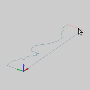
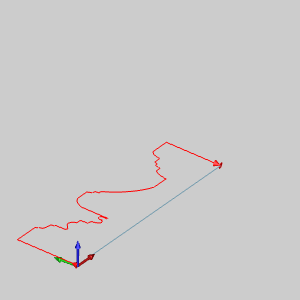
8 Click
the entity shown in the image below to set the start point and direction
of the Revolve Curve.
The Start arrow appears.
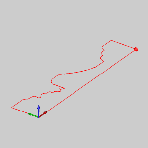
9 Hold
Shift and click the entity shown in the image below to set the end point
of the Revolve Curve.
The Preview appears.
Notice it is not the result obtained from Example 1. Since we have rotated
the wireframe, it's intended rotation axis is no longer parallel to the
X Axis.
10 In
the Rotation Axis group, click Pick Axis.
This will allow us to select the rotation axis for the function from geometry
in the graphics area.
The preview disappears.
11 Click
in the Rotation Axis list to give it focus.
The Rotation Axis list highlights to allow us to select the Rotation Axis.
12 Click
the entity shown in the image below.
Once selected, the Preview displays.

13 Click
OK to finalize the Revolve.
The surface is created in the graphics area and a
Revolve feature is created in
the![]() CAD Tree.
CAD Tree.
NOTE: Notice, even though we have With Caps selected, we have not created a solid. To create a solid that does not revolve a full 360 °, a closed chain needs to be selected as the Revolve Curve.
14 To end the function, click Cancel.
This concludes the examples.