The file opens.
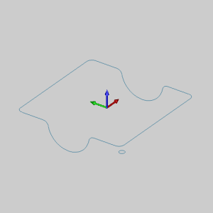
Leave the file in the ISO 2 view.
This example will demonstrate how to use the Sweep function.
NOTE: In the images below, the Show Axis X-Y toggle has been disabled in the Axis X-Y group of the Settings Part > Display dialog. The Gnomon has been used to show the Sweep Profile in the X,Y Plane.
1 In
the File menu, click Open.
2 In the Open dialog box, navigate to C:\BobCAD-CAM Data\BobCAD-CAM V**\Examples.
NOTE: This is the default install location. If you performed a custom install, navigate to the location in which you installed the software.
3 Select
Sweep_Surface_Example.bbcd, and
click Open.
The file opens.
Leave the file in the ISO 2 view.
4 Open
 Sweep by
selecting the function from Surfaces
menu.
Sweep by
selecting the function from Surfaces
menu.
The Sweep Surface parameters display in the Data Entry tab of the Data-CAM
Tree Manager and the Attachment Point list is given focus to accept selection
of a point or snap point.
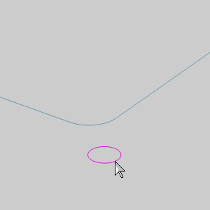
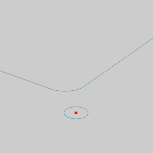
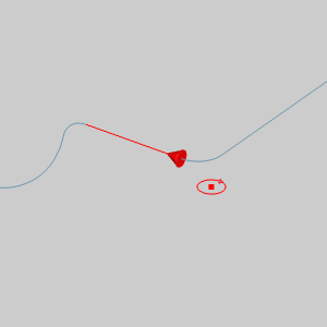
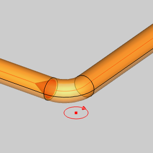
5 The first step is to select a point or snap point to assign as the Attachment Point of the Sweep Profile to the Sweep Path.
Press and hold Shift,
and click the small arc to display the snap points of the arc.
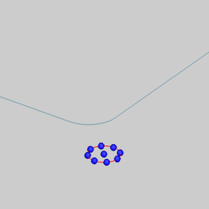
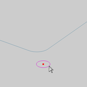
6 Click the snap point in the center of the arc to select it.
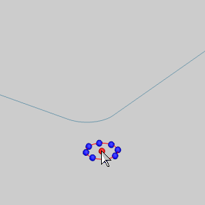
The point is added to the Attachment Point list and the focus is moved to the Sweep Profile list.
NOTE: When selecting the attachment point of the sweep profile, you don't always have to show the snap points first. You can click an entity near the snap point that you want to use and the software automatically selects the closest snap point of the entity. Showing the snap points may make the selection easier though for some geometry. With arcs, for example, you have to show the snap points to select the snap point at the arc center.
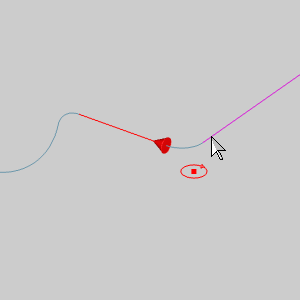
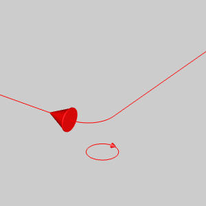
7 The next step is to select the Sweep Profile itself.
Press and hold Shift, and click the arc to select it define he profile geometry that is swept along the Sweep Path.
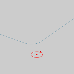
The chain is added to the Sweep Profile list
and the focus is moved to the Sweep Path list.
NOTE: Because our Sweep Profile is a single entity, we used chain selection to define the start and end of the profile in one click. If you were using a group of connected entities as the sweep profile, you can still use this method, or you can click the start entity first, and then hold shift and click the last entity to define the end of the sweep profile. This method is helpful when you have a group of connected entities, but you don't want to select them all. An example of this selection method is performed in the next step.
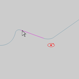
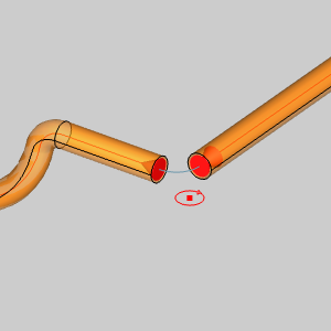
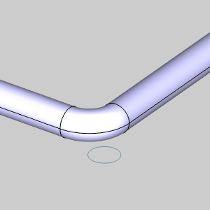
8 The next step is to select geometry as the Sweep Path. Because we are selecting a closed sweep path, we could just hold Shift and click anywhere along the path to select it and define the direction in one click. Instead, we use the two click method and skip an entity to show how it is done.
Click the end of entity shown below to set
the start of the sweep path.
The start arrow of the sweep path displays.
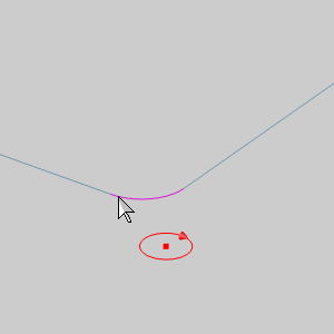
9 To
set the end of the sweep path, hold Shift
and click near the end of the entity shown below.
The Preview displays.
NOTE: Even though the chain for the sweep path is a closed path, we have selected the chain in such a way that we have avoided including a particular entity. Had we held Shift when clicking the first entity of the sweep path, all entities would have been included.
10 Next
to the Sweep Path list, click ![]() (Delete) to remove the partial chain from the list.
(Delete) to remove the partial chain from the list.
The Preview disappears.
11 Hold
Shift and select an entity of
the sweep path as shown below.
The Preview updates.
12 To
finalize this result, we would click OK. Before we do that, we will test
different Attachment Points by repeating the following three steps:
A Click
![]() (Delete) next to the Attachment
Point list to remove the existing point.
(Delete) next to the Attachment
Point list to remove the existing point.
The Preview and the Attachment Point disappears.
B Click
in the Attachment Point list to give it focus.
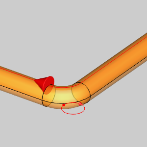
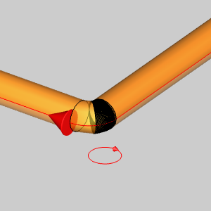
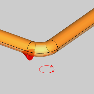
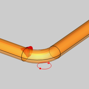
C With
the available snap points of an arc in mind, click one to test a new Attachment Point.
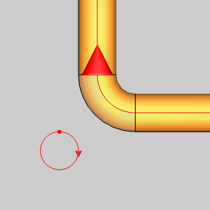
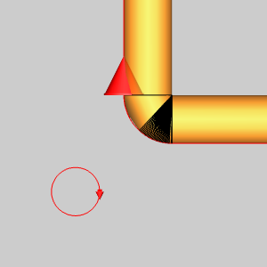
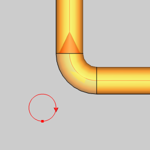
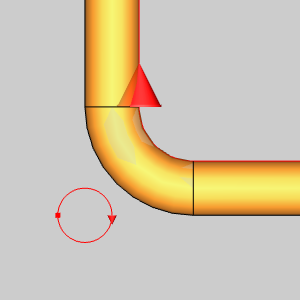
Repeat steps A,B, and C to get the following
results.
ISO 2 View |
ISO 2 View |
ISO 2 View |
ISO 2 View |
|
|
|
|
Top View |
Top View |
Top View |
Top View |
|
|
|
|
13 Click
OK to finalize the previewed result.
The surface is created in the graphics area and a
Sweep feature is created in the![]() CAD Tree.
CAD Tree.
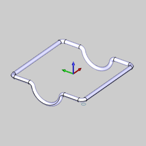
NOTE: The Result shown in the image above uses the center of the arc as the Attachment Point.
14 Click
Cancel to exit the function.
This concludes the example.