
The Break Entity function is used to break a single wireframe entity at the intersection of another wireframe entity (lines, arcs, splines, and/or points). To use the function, you first select the break entity, and then select the break at entity (or the intersecting entity at which the break entity is broken). After breaking an entity, it becomes two separate entities. This is helpful when modifying geometry or eliminating unwanted portions. The following is an example usage of the function. For help drawing entities to use with this example, view the CAD_Tutorials.
1 With the geometry in the graphics area, the first step for this example is to confirm the number of entities.
Right-click anywhere in the graphics area, and click Entity Summary.
Note the Quantity of Entities (2 in this example).
To close the dialog box, click OK.
2 In the Utilities menu, point to Break, and click Entity.
The Break at Entity parameters (Cancel only) display in the Data Entry tab of the Data-CAM Tree Manager.
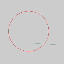
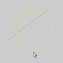
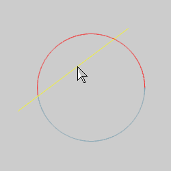
3 In the graphics area, point to the entity that you want to break so that it changes to the Highlight color.
Notice that the entire arc displays in the Highlight color. This shows that it is a single entity.
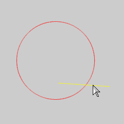
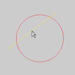
4 While the entity displays in the Highlight color, click to select it.
Notice that the arc changes to the Selection color.
The first selection defines the entity to break.
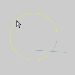
5 Click to select the next entity to define the intersection at which the arc is broken.
The arc is broken as soon as you click the second entity, there is no need to confirm the selection.
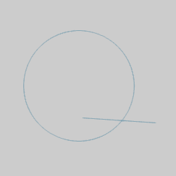
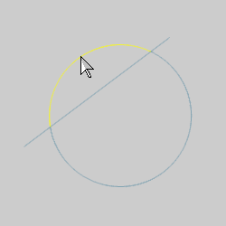
6 With the function still active, point to the arc.
Notice that the arc is now two entities (the entire arc does not display in the Highlight color).
7 To confirm, right-click anywhere in the graphics area, and click Entity Summary.
Note the Quantity of Entities (now 3 in this example).
8 To end the function, click Cancel.
When the break at entity intersects the break entity in more than one place, you can still use the function as explained in this topic. The only difference is that you can perform the function more than once if you want to break the entity at more than one intersection. Generally, the software breaks the entity at the intersection that is closest to the location you click (on the break entity). A quick example follows to help illustrate this.
Similar to the first example, a line intersects the arc in two places instead of one.
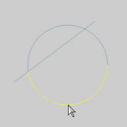
1 The arc is selected as the break entity, and the line is selected as the break at entity.
The arc is broken into two entities. Notice that this is the closest intersection to the location at which the arc was selected.
2 The process is repeated using the top half of the arc and the line. (If the lower half of the arc was selected, the function would fail, because there is no longer an intersection with the bottom arc.)
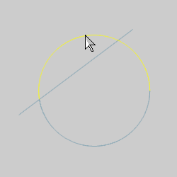
The upper arc is broken into two separate entities at the remaining intersection point.
IMPORTANT: This function only works if the entities share a common intersection. This is important when working with 3D wireframe drawings. It can be helpful to zoom-in closely and/or change to a different view to confirm that the entities do in fact intersect each other.
TIP: When selecting a point as the break location, the point does not have to intersect (or touch) the break entity. In this case, the function works like Break Screen meaning that the entity is broken perpendicular to the point.
This concludes the example.