The Trim Extend Screen function is used to trim an entity based on the location that you click in the graphics area. You first select the entity to trim, then click a location in the graphics area to trim the entity perpendicular to the point that you click.
For this example, you can sketch any wireframe geometry in the graphics area to use with the following steps. (For more help, view the CAD_Tutorials.)
In the Utilities menu, point to Trim Extend, and click Screen.
The Trim Screen parameters (Cancel only) display in the Data Entry tab of the Data-CAM Tree Manager.
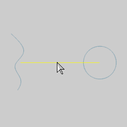
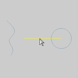
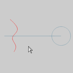
In the graphics area, point to an entity (so that it is displayed in the Highlight color), and click to select it.
This defines the entity to be trimmed (or extended).
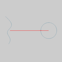
Notice that the entity changes to the Selection color after you click it. [These colors are set in the Settings Default (all new files) and the Settings Part (current file only) of the Preferences menu.]
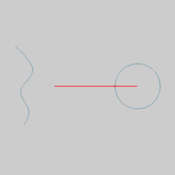
Click anywhere in the graphics area above or below (for the horizontal entity shown) the trim entity.
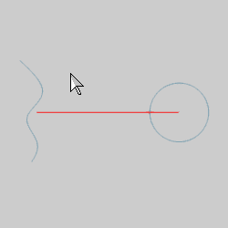
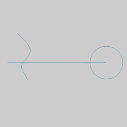
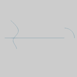
The entity it trimmed perpendicular (at a right angle) to the point that you click.
In addition to trimming entities, you can also extend entities, such as lines and arcs (they must be open shapes, not closed).
In the graphics area, select the same entity that was just trimmed.
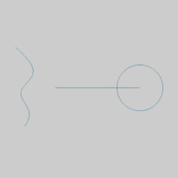
Click anywhere in the graphics area past (not above or below) the trim entity.
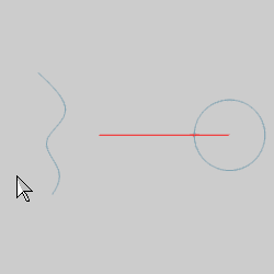
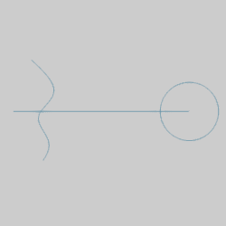
Notice that the entity is extended to the point (perpendicular to the point) that you click.
You can continue this process for as many entities as you want to trim or extend.
To end the function, in the Data Entry tab, click Cancel.
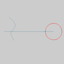
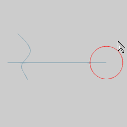
TIP: When using Trim Extend Screen, it is important to understand what to expect when trimming arcs, specifically 360 degree arcs or circles. (This information applies to any arc, but we use a full circle to explain.) When you create circles, unless you specify a start and end angle, they are automatically broken at the zero degree location (the 3 o'clock position). When you trim a circle, the location that you click to select the circle (before trimming) defines how the circle is trimmed. The following images show the location clicked and the result of trimming the circle shown in this example.
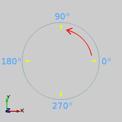
The following image shows the angles and positive direction of rotation used when creating an arc.
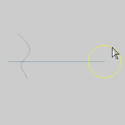
When selecting the arc, if you click the arc at a point that is before the trim point, the arc is trimmed from the trim point (from the end of the arc). If you click to select a point that is after the point at which you will trim the arc, the arc is trimmed to the trim point (from the start). The following examples are shown to better explain what this means.
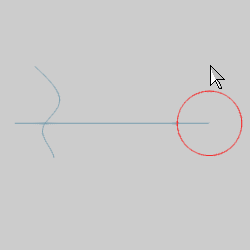
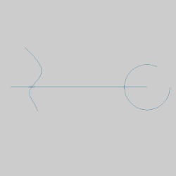
For the first circle example, when selecting the arc, we click a location that is before the trim point.
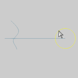
To elaborate on the example, this time we select a point that is after the trim point to have the circle trimmed from the start. (To undo the previous trim, press Ctrl+Z, or in the Edit menu, click Undo.)
This concludes the example.