The Default Features are used to set global settings for the individual operations being completed while inside the Nesting Wizard. After the nest has been computed, you may need to modify certain operations to accomplish what is needed. Adding pocket operations is a good example. In the Nesting Wizard, you don't want to make everything a pocket, but afterwards you would need to modify one of the profiles into a pocket. This lesson will show you how to customize operations.
The BobCAD part file for this tutorial is available here C:\BobCAD-CAM Data\BobCAD-CAM V**\Examples\Customizing_Tutorial2.bbcd. The file already has a Nesting Job completed in the CAM Tree. In this example, you learn how to edit the machining strategy of several inner profile features to create a stepped pocket.
1 Open the part file Customizing_Tutorial2.bbcd
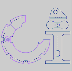
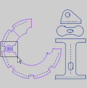
2 Take note of the Nesting Job example below. This
Nesting Job has four nested parts. The nested parts each have an inner
and outer profile, hole, and dado. In the example below you can see how
each part can have it's various components expanded or minimized. All
items in blue will have context menus available if you right-click on
them in the Nesting Job. For this example, left-click an item below to
see the context menu associated with that item as it would appear when
you right-click on it in the CAM Tree.
![]() Nesting Job
Nesting Job

![]() Default Operations
Default Operations


![]() Profile
Profile
![]() Drill Hole
Drill Hole
![]() Profile
Profile
![]() Hole -
Hole -
![]() Hole -
Hole -

![]() Hole -
Hole -
3 In
your CAM Tree, click the minus symbol next to Part 1, Part 2, and Part
3 to minimize the contents of the parts.
4 Click
the plus symbol next to Part 4 in order to maximize the contents. Part
4 will highlight in the CAD Window.
5 Hold
Ctrl on your keyboard and drag a window around the inner profiles of Part
4 in order to zoom into that area.
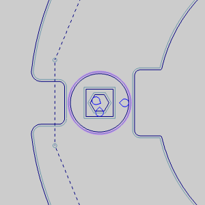
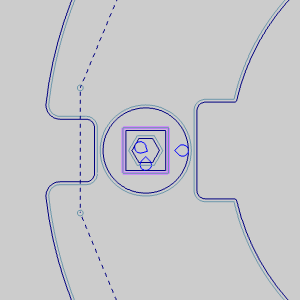
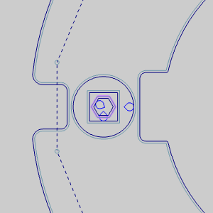
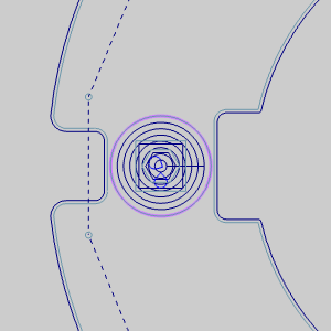
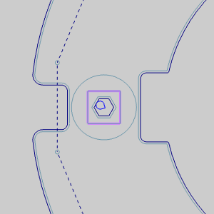
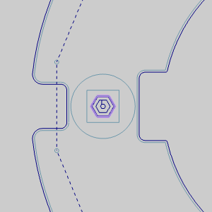
6 Notice
that Part 4 has three separate inner profiles. Take a moment to click
on each Inner Profile in the CAM Tree to see the associate geometry.
|
|
|
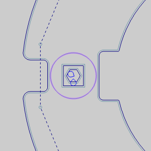
7 When
setting up the nest we have assigned all of our geometry that was on the
CAD layer to be handled as profile geometry. While the rest of our geometry
has been assigned the desired operations, this has given us three
inner profiles, one inside of the other where we need a stepped pocket.
Right-click on the first Inner Profile of Part 4 in the CAM Tree and select
Customize to unlock the profile and allow editing.
8 Right-click
the first Inner Profile again and select Edit to launch the Mill 2 Axis
Wizard.
9 Change
the Total Depth to 0.2500 and click Next>> to move on to the Machining
Strategy page.
10 We
need to alter the type of operation that is being done on the inner geometry,
so click on the ![]() button under
Current Operations to eliminate the Profile Rough operation.
button under
Current Operations to eliminate the Profile Rough operation.
11 In
the Available Operations group, highlight Pocket and click ![]() to move it to the Current
Operations group and then click Compute at the bottom right of the Mill
2 Axis Wizard.
to move it to the Current
Operations group and then click Compute at the bottom right of the Mill
2 Axis Wizard.
12 Right-click
the first Inner Profile and select Blank/Unblank Toolpath to hide our
result.
NOTE: The nest will recalculate every time you click Compute. Since this nest does not have an exceedingly long calculation time, computing after every alteration, as we will do, is not out of the question. Keep this in mind if you ever need to alter several features in a nest that has taken a lot of time to compute. In those situations, it may be advisable to make a change, and click Finish instead of Compute after every edit. Once all editing has been completed, compute to calculate all the edits at once.
1 Right-click
on the second Inner Profile and select Customize to unlock the profile
and allow editing.
2 Right-click
the second Inner Profile again and select Edit to launch the Mill 2 Axis
Wizard.
3 The operation we are creating now will be starting inside of the previously finished operation. Since the previous operation has already been completed to a depth of 0.2500, there is no reason to start at 0.0000. In this case, change the Top of Feature to -0.2500,set the Total Depth to 0.2500 and click Next>> to continue to the Machining Strategy page.
IMPORTANT: Total Depth is an incremental value from the Top of Feature.
4 We
are, again, altering the type of operation that is being done on the inner
geometry, so click on the ![]() button under Current Operations to eliminate the Profile Rough operation.
button under Current Operations to eliminate the Profile Rough operation.
5 In
the Available Operations group, highlight Pocket and click ![]() to move it to the Current
Operations group and then click Compute at the bottom right of the Mill
2 Axis Wizard.
to move it to the Current
Operations group and then click Compute at the bottom right of the Mill
2 Axis Wizard.
6 Right-click
the second Inner Profile and select Blank/Unblank Toolpath to hide our
result.
1 Right-click
on the third Inner Profile and select Customize to unlock the profile
and allow editing.
2 Right-click
the third inner profile again and select Edit to launch the Mill 2 Axis
Wizard.
3 The
operation we are creating now will be starting inside of two other finished
operations. Since the previous operations have already been completed
to a combined depth of 0.5000, there is no reason to start at 0.0000.
In this case, change the Top of Feature to -0.5000, set the Total Depth
to 0.5000 and click Next>> to continue to the Machining Strategy
page.
4 We
are, again, altering the type of operation that is being done on the inner
geometry, so click on the ![]() button under Current Operations to eliminate the Profile Rough operation.
button under Current Operations to eliminate the Profile Rough operation.
5 In
the Available Operations group, highlight Pocket and click ![]() to move it to the Current
Operations group.
to move it to the Current
Operations group.
6 In
the Available Operations group, highlight Profile Finish and click ![]() to move it to the Current Operations group and then
click Next>>.
to move it to the Current Operations group and then
click Next>>.
7 Click![]() Finish in the tree on the left side of the Mill 2 Axis
Wizard to move on to the
Finish in the tree on the left side of the Mill 2 Axis
Wizard to move on to the ![]() Finish
page.
Finish
page.
8 Manually
alter the Diameter value in Tool Data from 0.5000 to 0.1250 and click
Compute at the bottom right of the Mill 2 Axis Wizard.
Currently we only have one toolpath visible. However, even when all the toolpath is visible, and viewed in an isometric view it can be hard to tell exactly what we will end up with. In this step we will view the simulation to verify we have the stepped pocket programed correctly.
1 Right-click
the Nesting Job and select Simulation.
2 Press
 play.
play.
3 Once
you see the pocket in our part starting to get cut, press  pause, make sure that you
are in an
pause, make sure that you
are in an  isometric view and zoom in to the pocket
so you can see it clearly.
isometric view and zoom in to the pocket
so you can see it clearly.
4 Make
sure that you have the speed low enough to be able to see what is happening,
and Press play.
5 Notice
that when the first pocket is complete, the tool lifts, moves over to
the X,Y coordinates for the entry point of the next pocket, moves down
to the feed plane and feeds into the material.

This is what we accomplished by setting our Top of Feature at the completed
depth of the previous feature. Had we left the Top of Feature at default
and entered only the desired depth in the Total Depth field we could have
had instances where the tool was completing needless feed moves through
material that had been removed previously.