In this Topic Show
This tutorial is designed to highlight some of the key areas of the BobCAD-CAM’s nesting module. In this example, we will cut some inner and outer profiles from the sheet.
The BobCAD part file for this tutorial is available here C:\BobCAD-CAM Data\BobCAD-CAM V29\Examples\New_Nesting_Tutorial1.bbcd. In this example, you learn how create a Nesting Job of several basic parts.
For every nest that is created, you will need to create a job and select what parts need to be nested for the job. When it comes to picking geometry you can either select geometry that is already open in your CAD window, load geometry from existing files that have not yet been open, or a combination of both. In this case, we will select geometry that is already open in the CAD window.
1 Open
the New_Nesting_Tutorial1.bbcd file from the C:\BobCAD-CAM Data\BobCAD-CAM
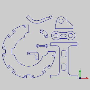
V28\Examples folder. Note that when creating a nest, the original
location of the parts is not important. The parts in this file have
been moved off to left because we will be setting up our sheet in the
X+,Y+ quadrant. This will make things a little easier to see once the
nest has been completed.
2 Once
open, click the CAM tree tab in the Data-CAM Manager.
3 Right
click CAM Defaults, and click New Job. Under Job type, select Nesting
and click Nesting Wizard. The Nesting Wizard displays.
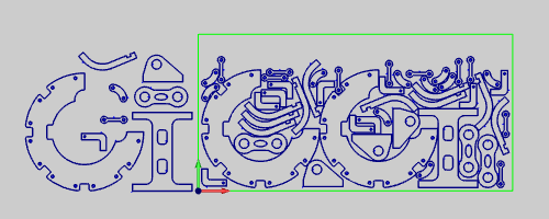
The first page of the Nesting Wizard allows you to associate the parts to the Nesting Job. In this example, all of the nesting parts are already open in the CAD window, so we simply select them using the Select Geometry option. If the nesting parts are contained in separate part files, you can choose the Load Files option to find the folder location and add the separate part files to the Nesting Job.
1 Click
the Select Geometry button. The Nesting Wizard hides, and selection
mode is activated.
2 Drag
a window around all of the parts in the workspace.
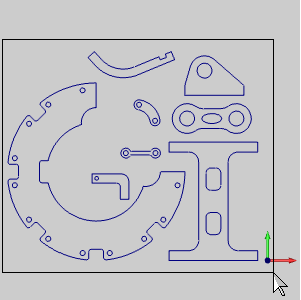
3 Once
all of the parts are highlighted, right click in the workspace and click
OK to confirm the part selection.
IMPORTANT: The window selecting geometry is not recommended unless you are absolutely sure the geometry is clean. If you are not sure the geometry is clean, use a chain selection method to pick one chain at a time. Find out more about chain selection here.
4 The
Nesting Wizard returns, and the eight separate parts are listed in the
Part List area.
Once all the parts have been selected for the nest, the next page will
allow you to set the individual part parameters. In the Part Parameters
page, you can rename parts, set their quantities, priorities, rotation
options and advanced parameters.
1 Now
that the parts are associated with the Nesting Job, click the Next button
to move to the Parts Parameters page.
2 For
this example, the only thing we will alter on the Part Parameter page
is the quantity for each part. Notice that Part 1 is already highlighted.
In this case we want the first four parts to have a quantity of ten. Hold
Shift on your keyboard and click Part 4. Notice the first four parts are
now highlighted.
3 Below
the Part List, in the Part Parameter group, change the quantity to 10.
4 Now
alter the quantities of the remaining parts to match the following:
Part |
Quantity |
Part 5 Part 6 Part 7 Part 8 |
3 3 1 2 |
5 Once the quantities have been set, click Next>> to continue to the Tabs page and once again to continue to the Sheet Parameters page.
For every nesting job, you will need to define the stock that will be used to nest the parts on. The Sheet Parameters page will allow you to set the sheet name, length, width, height, quantity, add various sheet types and quantities, and even set some advanced parameters.
1 Take
note of the length, width and height of the sheet.
In this case we have exactly what we want to use. While we will leave the
length at 96, the width at 48, and the height at 1, we will make to the
sheet is its name.
2 Double-click
on Sheet-1 in the Sheet List under Sheet Name.
Notice the focus is on the sheet name and it is now able to be edited.
3 Change
the sheet name from Sheet-1 to Tutorial.
4 In
the Additional Sheet Parameters group click Set Stock Margin to launch
the Stock Margin dialog box.
5 Set
the Uniform Stock Margin to 1.0000 and click OK.
6 Click Default Profile in the tree on the left side of the wizard to jump to the Default Profile page.
For every nesting job, you will need to go through to set your depth of cut, tool, and cutting parameters. The Default Profile will allow you to set all the parameters necessary to cut the parts in the manner you intend for them to be cut.
1 From
part four, we know that the stock we have set up is one inch thick. So
in this case we will want our depth to match the height of our sheet.
Set the Total Depth to 1 and click Next>> to go the Machining Strategy
page.
2 The
machining strategy is set to Profile Rough by default. We will leave this
job as a one pass job, so there is no need to add any other operations.
Click Next>> to go to the Posting page.
3 In
this case, we will not be changing the work offset, and we are not using
a contour ramp, so we will leave these settings as they are. Click Next>>
to go to the Rough page.
4 For
this tutorial we will be entering the tool manually. Change the Diameter
value from 0.5000 to 0.2500. The only other option we will want to change
is to give our cuts a lead in and a lead out. Click Leads in the tree
on the left side of the wizard to go to the Leads page. For more information
on tools see The Mill Wizard Tool Setup.
5 Select
the Blend option under Lead-in and set the radius to 0.125. Notice in
the Lead-out group the check box for Same as Lead-in is already selected.
This will keep us from having to set the Lead-out, so long as we want
it to be the same as the lead-in.
6 Click
Compute at the bottom right of the Wizard.
Although we have set a default method to all profiles, there will be
instances where particular profiles need to be handled differently. A
good example is when one of the parts has an inner profile that we need
to have handled as a pocket. For this tutorial we will be altering Part
5 to turn its inner profile into a pocket.
1 In
the CAM Tree, click the plus sign next to Part 5 to maximize its contents.
2 We
can now see the part consists of an Outer Profile and an Inner Profile.
Right-click on the Inner Profile. Once you right-click, you will see that
the option for Edit is not available. Select Customize.
3 Right-click
on Inner Profile again and notice that the Customize option has been replaced
with Use Default. The Edit option is now available. Select Edit.
4 The
Mill 2 Axis Wizard is launched. On the feature page, alter the Total Depth
to our required pocket depth of 0.7500 and click Next>>.
5 We
need to alter the type of operation that is being done on the inner geometry,
so click on the  button under
Current Operations to eliminate the Profile Rough operation.
button under
Current Operations to eliminate the Profile Rough operation.
6 In
the Available Operations group, highlight Pocket and click  to move it to the Current
Operations group and then click Compute at the bottom right of the wizard.
to move it to the Current
Operations group and then click Compute at the bottom right of the wizard.
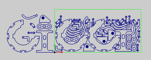
7 The
Nest is recomputed and the toolpath result is shown.
Now that the nest has been generated, we will want to make sure all the parts quantities fit on the sheet, and that there are no issues with the cuts in the simulation.
1 In
the CAM Tree, right-click on  Sheets and select Show Summary.
2 Here
we can see we have no leftover parts. In this case all of our parts have
been nested. This summary will also give us an idea of how much of the
sheet we have used. Click OK to close the Nesting Summary.
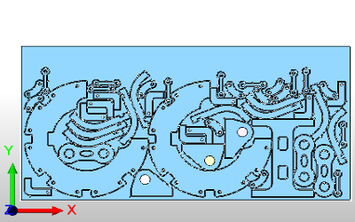
3 Right-click
on the Nesting Job and select Simulation to enter into the simulator to
check the final result. The image below is the final result. Learn more
about the simulation here.
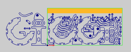
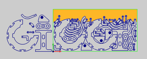
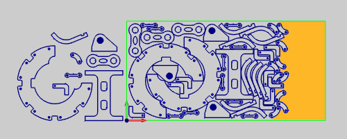
Now that the machining we intend to do has been verified in the simulation, the only other question would be whether or not we are satisfied with the final nested result. While it is true that we have managed to fit all of our requested parts on the sheet, we may want to use the portion of the sheet with no parts nested on it for future nests. This would be referred to as a remnant sheet. BobCAD-CAM users that have the Pro version of our Nesting package have a lot of tools to get this done a little cleaner, but even Standard users are able to utilize remnants themselves. Let us look at our nested result and what area of the sheet remains to possibly use in the future.
While there is some space at the top, which is visualized in the next image, there is not a lot of room for larger parts. Lets see if we can adjust the nest to produce a wider area.
1 Right-click
on the Nesting Job and select Edit to get back into the Nesting Wizard
to make one small adjustment.
2 Now
click on the Sheet Parameters in the tree on the left side of the wizard
to jump to Sheet Parameters page.
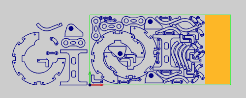
3 In
the Additional Sheet Parameters group change Fill Sheet from Vertical
(Y) to Horizontal (X) and click Compute at the bottom right of the wizard
to compute those changes.
Shown here you can see the actual usable material from one result to the next
Vertical (Y) |
Horizontal (X) |
|
|
Once the nested result has been finalized it will be time to produce the code to send to the machine.
1 In
the CAM Tree, Click the plus symbol next to Sheets
to show its contents.
2 Click
the plus symbol next to  Tutorial
to show its contents.
Tutorial
to show its contents.
3 Right-click
Tutorial-1 under the main Tutorial sheet type and
select Post Sheet.
4 The
code is posted in the Layer-UCS-Post Manager.
5 Right-click on the code in the Layer-UCS-Post Manager to select Save As or Edit CNC. With this method, you can either save to a particular file location or to open in Predator Editor respectively.