The 2 Axis Chamfer Operation
Introduction
This topic explains the Chamfer operation parameters found in the 2 Axis Wizard.
 Patterns
Patterns
Standard is the only pattern available for chamfer operations.
Compensation
System Compensation
With this option On, the system offsets the geometry by the tool radius. With this option Off, you should use Machine Compensation.
-
- Off- the toolpath is calculated from the center line.
- Left- the toolpath is calculated to the left of the selected contour.
- Right- the toolpath is calculated to the right of the selected contour.
Machine Compensation
These options only effect the output in the posted code.
-
-
Off- no cutter compensation codes are output in the posted program.
-
Comp Left (G41) - the toolpath of the operation represents the center of the cutter. The post processed code includes the command for cutter compensation to the left of the contour.
-
Comp Right (G42) - the toolpath of the operation represents the center of the cutter. The post processed code includes the command for cutter compensation to the right of the contour.
-
Parameters
Tool Position
-
Cutter Position - sets the distance away from the center of the toolpath to begin the cut, in order to use a chamfer tool that does not have flutes that extend all the way to the tip.
-
Small Diameter - sets the width of the bottom of the chamfer tool when Flat Bottom Tool is selected.
- Chamfer Angle - sets the
angle of the chamfer for Sharp Tool or Flat Bottom Tool.
 Sharp Tool
- is used if the chamfer tool has a sharp point.
Sharp Tool
- is used if the chamfer tool has a sharp point. Flat Bottom
Tool - is used if the chamfer tool has a flat bottom; enables
the Small Diameter box.
Flat Bottom
Tool - is used if the chamfer tool has a flat bottom; enables
the Small Diameter box.
Depth
- Chamfer
Depth - enables the Depth box to create the chamfer based on
its vertical depth.
-
- Depth - sets the vertical depth of the chamfer.
- Pick Bottom - enables selection mode for you to set the depth by selecting geometry.
- Chamfer
Length - enables the Length box to create the chamfer based
on the length of the chamfered edge.
-
- Length - sets the chamfer length along the chamfered edge.
- Chamfer
Width - enables the Width box to create the chamfer based on
its horizontal width.
-
- Width - sets the horizontal chamfer width.
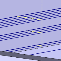
Method
-
Single Step
- the Total Depth value is processed in one pass.
-
Multiple Steps - the
Total Depth and Depth of Cut values are used to generate the number
of equal cuts used to process the profile operation. This enables
the following four options.
-
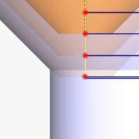
Depth of Cut - When using Multiple Steps, this is the depth at which all passes, prior to the final depth, will be taken.
 Click
here to see an example.
Click
here to see an example. -
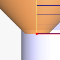
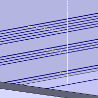
 Stepover -
will add side roughing steps to each Depth of Cut prior to
the final depth. The value entered will set the step over
amount which all steps, prior to the final step, will use.
Click
here to see an example.
Stepover -
will add side roughing steps to each Depth of Cut prior to
the final depth. The value entered will set the step over
amount which all steps, prior to the final step, will use.
Click
here to see an example.
![]() Stepover - With
this check box cleared, no stepover will be used.
Stepover - With
this check box cleared, no stepover will be used.
-
Sort by - allows you to choose, in which order, the depths and steps are to be handled.
-
Passes - sets the order to complete all depths on the first step, before moving onto the next step.
-
Slices - sets the order to complete all the steps on the first depth, before moving onto the next depth.
-
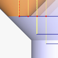
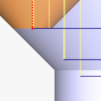
Minimize Retracts - Selecting the Minimize Retract check box helps prevent the tool from lifting back up to the rapid height before the next cut.
-
Link with Rapid - will connect the passes with a rapid move at depth. With this option cleared, the link will be a feed move.
![]() Click here to see an example of
Minimize Retracts.
Click here to see an example of
Minimize Retracts.
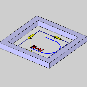
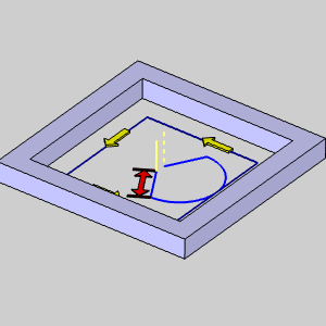
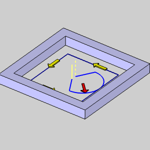
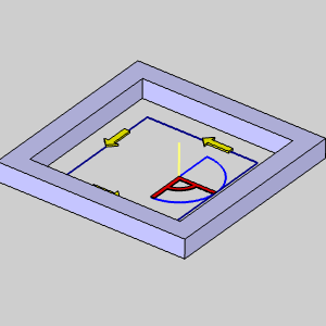
Normally, at the end of a pass, the tool retracts to the rapid plane, moves to the X, Y position of the next cut, rapids down to the feed plane, feeds to the proper depth, then starts the next pass. Minimize Retracts will help to eliminate moves back to the rapid plane between passes with a few exceptions: If the direct link intersects with any part of the toolpath chain, the toolpath will go to the rapid plane between passes. If the direct link is on the opposite side of the offset direction, the toolpath will go to the rapid plane between passes. When no offset direction is set by system or machine compensation, left side compensation is assumed by the system.
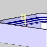
Leads
Material Entry
- Plunge - generates a plunge feed move into the beginning of the lead-in type.
Leads
The 2 Axis Leads
The 2 Axis Leads
Introduction
This topic explains the leads options and parameters for the 2 Axis operations: Profile Rough, Profile Finish, Chamfer Mill, and Corner Round. The leads parameters for all other 2 Axis operations are explained in their respective topics.
Using Machine Compensation with Leads: When defining lead moves that use a radius (Circular or Blend), the Radius value of the lead move must be equal or greater than the tool radius to avoid an error at the machine control. Also, for any lead type, Machine Compensation requires a linear move with a length that is equal or greater than the tool radius in order to properly apply the tool compensation commands.
Entry
Lead-in
Click the name of each lead type in the following descriptions to view an example image.
-
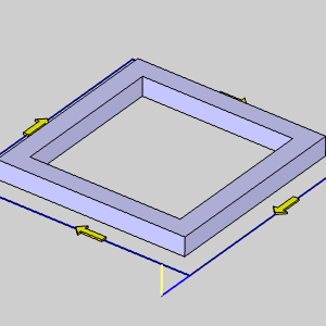
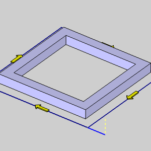
Vertical
- generates a plunge feed move into the feature.

The Vertical Lead-in type is not actually a lead-in as it only creates a plunge move into the feature. Most machine controllers cannot apply compensation commands to a vertical plunge (Z-axis) move. (G41/G42 are not output when using the Vertical Lead-in.)
-
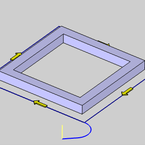
Parallel
- generates a linear feed move into the feature parallel to the toolpath
using the specified length.
-
Length - sets the length of the lead-in from the feature.
-
Right
Angle - generates a linear feed at a right angle to the
toolpath using the specified length.
-
Length - sets the length of the lead-in from the feature.
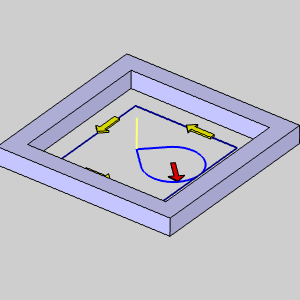
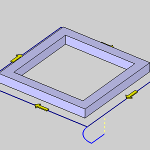
-
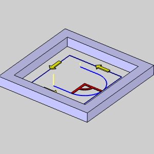
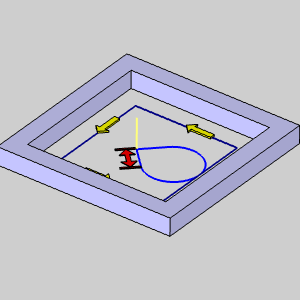
Circular
- creates a linear move followed by an arc sweep into the start of
the feature. You have complete control over both the line move and
the arc move using the following settings.
- Right Angle - sets the Angle of the line at 90.00 degrees to the start of the arc.
- Tangent - sets the Angle of the line to 0.00 degrees to the arc to make the line and arc tangent.
- User Defined - enables the Angle parameter for you to customize the angle of the circular lead.
The three previous options all provide the following settings to define the lead-in.
Line
- Angle
- sets the angle of the line move into the start of the arc
move when using User Defined.
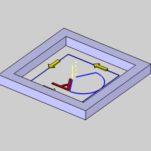
- Length
- sets the length of the line segment for the lead-in move.
Arc
- Radius
- sets the radius of the arc sweep into the start of the feature.
- Sweep Angle
- sets the length of the sweep based on the angle of the arc.
-
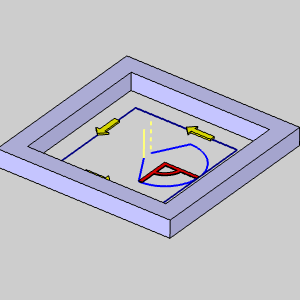
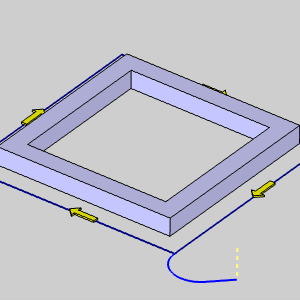
Blend
- generates a linear move and then an arc move into the feature. This
lead type can be used to lead-in and lead-out of the feature from
the same point. The blend lead type creates a tangent path into the
feature.
Lead-out
Click the name of each lead type in the following descriptions to view an example image.
-
Same As Lead-in
Select this check
box to use the Lead-in settings to automatically set the Lead-out settings.
![]() Clear the check box to set the Lead-out independently from the Lead-in.
Clear the check box to set the Lead-out independently from the Lead-in.
-
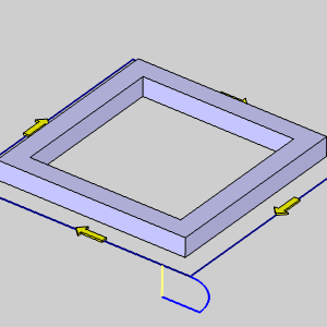
Vertical
- generates a plunge feed move out of the feature.

The Vertical Lead-out type is not actually a lead-out as it only creates a vertical retract out of the feature. Most machine controllers cannot apply compensation commands to a vertical retract (Z-axis) move. (G41/G42 are not output when using the Vertical Lead-out.)
-
Parallel
- generates a linear feed move out of the feature.
-
Length - sets the length of the lead-out from the feature.
-
Right
Angle - generates a lead-out at a right angle to the toolpath.
-
Length - sets the length of the lead-out from the feature.
-
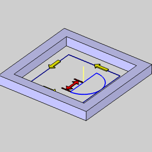
Circular
- creates an arc sweep followed by a linear move out of the feature.
You have complete control over both the line move and the arc move
using the following settings.
- Right Angle - sets the Angle of the line at 90.00 degrees to the end of the arc.
- Tangent - sets the Angle of the line to 0.00 degrees to the arc to make the line and arc tangent.
- User Defined - enables the Angle parameter for you to customize the angle of the circular lead.

The three previous options all provide the following settings to define the lead-out.
Line
Arc
- Radius -
sets the radius of the arc sweep out of the feature.
- Sweep Angle
- sets the length of the sweep based on the angle of the arc.
-
Blend
- generates a linear move and then an arc move out of the feature.
This lead type can be used to lead-in and lead-out of the feature
from the same point. The blend lead type creates a tangent path out
of the feature.
-
Overlap Amount - sets the length of overlap between the start point and end point of the toolpath to change the lead-in and lead-out locations.
Related Topics
The Milling Wizard
The 2 Axis Operations
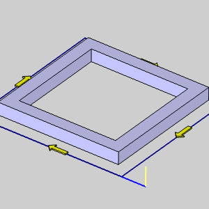
The Corner Rounding Operation
Corner Types
External Corners
-
-
Sharp - creates a sharp corner.
-
Round - creates a round corner.
-
Loop Radius - cuts a corner using a loop of a specific radius.
-
-
% - changes the Radius box value from a specific radius of the loop to a percentage of the tool diameter.
-
Radius - sets the size of the loop radius.
-
-
-
-
Loop Length - cuts a corner with a loop of a specific length.
-
-
Length - sets the length of the loop.
-
-
Triangle - uses a straight line to connect the passes joining the toolpath segments around a corner.
-
-
Length - sets the length past the corner that the toolpath extends before connecting to the next segment.
-
-
Bisect Line - relieves a corner by extending a line outward from the corner and then returning to the programmed path.
-
-
Length - sets how far away from the corner the Bisect Line extends.
-
-
The four preceding Corner types also use the following settings:
-
Min Angle - sets the minimum included angle of a corner for which the selected Corner Type is applied.
-
Max Angle - sets the maximum included angle of a corner for which the selected Corner Type is applied.
Internal Corners
-
Sharp - creates a sharp corner.
-
Round - creates a round corner.
-
Loop Radius - cuts a corner using a loop of a specific radius.
-
- % - changes the Radius box value from a specific radius of the loop to a percentage of the tool diameter.
- Radius - sets the size of the loop radius.
- Loop Length - cuts internal corners with a loop of a specific length.
-
- Length - sets the length of the loop.
-
Triangle - uses a straight line to connect the passes joining the toolpath segments inside a corner.
-
-
Length - sets the length from the corner that the toolpath extends before connecting to the next segment.
-
-
Bisect Line - relieves an internal corner by extending a line inward from the corner and then returning to the programmed path to continue.
-
-
Length - sets how far away from the corner the Bisect Line extends.
-
The four preceding Corner types also use the following settings:
-
Min Angle - sets the minimum included angle of a corner for which the selected Corner Type is applied.
-
Max Angle - sets the maximum included angle of a corner for which the selected Corner Type is applied.
MDI (Manual Data
Input)
View the MDI topic.
Related Topics
The Milling Wizard