Tool Library - Lathe Threading Tool
Introduction
This page will allow you to create new, or modifying existing inserts and tool holders. This page will also allow you to assign Tool Numbers and Offsets, Spindle Direction and Coolant options, as well as Speeds and Feeds.
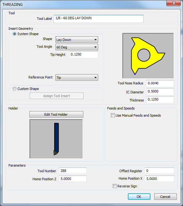
Tool
Tool Label - adds a name to the tool, in the tool list, that allows you to easily identify the tool.
Insert Geometry
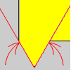
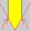
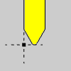
![]() System Shape
System Shape
|
|


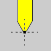
![]() Custom Shape
Custom Shape
-
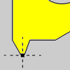
Assign Tool Insert - When Custom Shape is selected, clicking the Assign Tool Insert button will hide the Tool Library and allow you to select Tool Insert geometry from the Workspace.

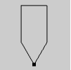 |
When assigning insert geometry, be sure to have the reference point defined as a point, and any interior geometry drawn as a dotted line as shown.
|
Holder
- Edit Tool Holder - will launch the Tool Holder Definition dialog box to allow you to specify measurements for the holder, or select geometry from the Workspace in order to define the holder.
Feeds and Speeds
![]() Use Manual Feeds and Speeds - Selecting this check box will give
you access to the following parameters. These will allow you to set specific
Feeds and Speeds for the insert. When the insert is used in the Lathe
Wizard, these will be the values that are automatically entered for the
tool.
Use Manual Feeds and Speeds - Selecting this check box will give
you access to the following parameters. These will allow you to set specific
Feeds and Speeds for the insert. When the insert is used in the Lathe
Wizard, these will be the values that are automatically entered for the
tool.
-
 RPM - sets the feeds and speeds to
revolutions per minute.
RPM - sets the feeds and speeds to
revolutions per minute. -
 CSS - sets the feeds and speeds to a constant
surface speed.
CSS - sets the feeds and speeds to a constant
surface speed. -
Maximum RPM - sets the limits of the spindle speed in the posted NC program.
-
Spindle RPM/SFM - sets the spindle speed for the feature in revolutions per minute or the surface feet per minute based on the selected RPM/CSS option.
-
Feedrate - sets the feedrate for the feature.
Machining Data
-
Tool Number - sets the assigned tool number.
-
Home PositionZ - sets the Home Position in Z for the tool.
-
Offset Register - sets the register on the machine that stores the diameter offset values for the tool.
-
Home PositionX - sets the Home Position in X for the tool.
-
 Reverse
Sign - reverses the output of the X value. Selecting this check
box will designate a move toward the center of rotation as negative
move and a move away from the center of rotation a positive move.
Reverse
Sign - reverses the output of the X value. Selecting this check
box will designate a move toward the center of rotation as negative
move and a move away from the center of rotation a positive move.
Important : Since we draw our lathe parts in the upper left quadrant of the Workspace, there can be some confusion when tools are used that move toward the center of rotation from under the part. As long as those tools move toward the center of rotation with a positive value, nothing special needs to be done. There are some tools that move toward the center of rotation with a negative value and these are the tools that the Reverse Sign check box is for. Select the Reverse Sign check box and the X moves for this tool only will be reversed.